 | –≠–ª–µ–∫—Ç—Ä–æ–Ω–Ω—ã–π –∫–æ–º–ø–æ–Ω–µ–Ω—Ç: S7131SF | –°–∫–∞—á–∞—Ç—å:  PDF PDF  ZIP ZIP |

KSD-I5C008-001
1
S71xxSF
Standard Voltage Detector
7
Description
∑ The S71xx prevents the error of system from supply voltage below normal voltage level at the time the power on
and instantaneous power off in systems.
Features
∑ Current Consumption is Low (I
CCL
=300 Typ. I
CCH
=30 Typ.)
∑ Resetting Output Minimum Guarantee Voltage is Low (0.8V Typ.)
∑ Hysteresis Voltage is Provided (50 Typ.)
Applications
∑ As Control Circuit of Battery-Backed Memory
∑ As Measure Against Erroneous Operations at Power On-Off
∑ As Resetting Function for the CPU-Mounted Equipment --- PC, Printer, VTR, Fax, C-TV etc.
∑ As Measure Against System Runaway at Instantaneous Break of Power Supply etc.
Ordering Information
Type NO.
Marking
Package Code
S71xxSF
7
SOT-23F
: Detecting Voltage Code
Outline Dimensions
Unit : mm
S
S
e
e
m
m
i
i
c
c
o
o
n
n
d
d
u
u
c
c
t
t
o
o
r
r
PIN Connections
1. OUT
2. Vcc
3. GND
0.
45 Max.
0.
10 Max.
3
1
2
1.
90 T
y
p
.
2.
80~3.
00
2.30~2.50
0.
80~1.
00
1.50~1.70
0.
20 Max.
Equivalent Circuit Diagram
KSD-I5C008-001
2
S71xxSF
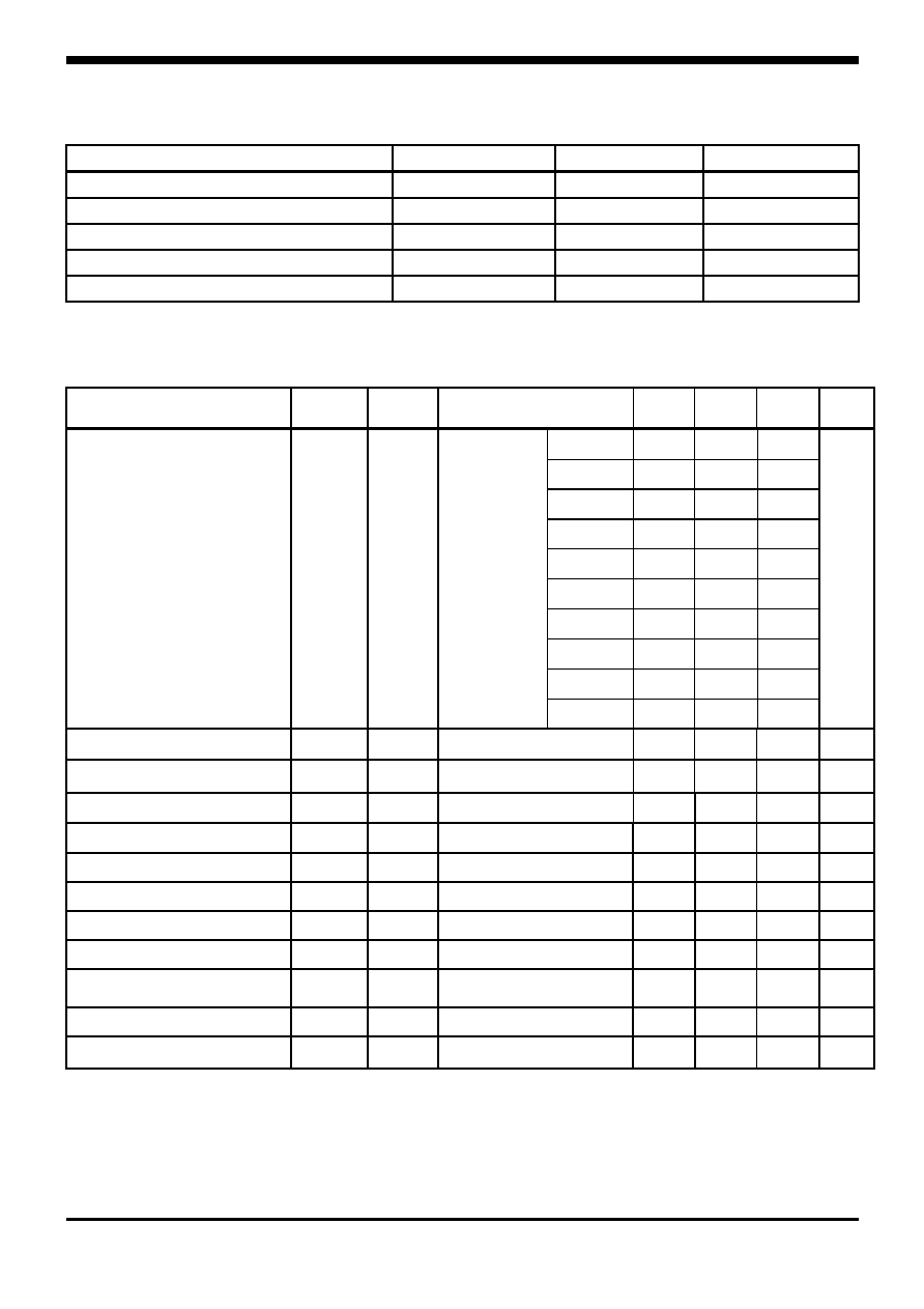
Maximum ratings
(Ta=25
∞C)
Characteristic Symbol
Ratings
Unit
Supply Voltage
V
CC
-0.3 ~ +15
V
Power Dissipation
P
D
* 300 mW
Output Voltage
V
OUT
-0.3 ~ +15
V
Operating Temperature Range
T
OPR
-30 ~ +75
Storage Temperature Range
T
STG
-55 ~ +150
* With PCB(8◊8 Copper Area) at Glass Epoxy Board (t=1.7 , Area; 20◊20 )
Electrical Characteristics
(V
CC
=5V, Ta=25
∞C)
Characteristic Symbol
Test
Circuit
Test Condition
Min.
Typ.
Max.
Unit
S7145SF 4.35 4.5 4.65
S7142SF 4.05 4.2 4.35
S7139SF 3.75 3.9 4.05
S7136SF 3.45 3.6 3.75
S7133SF 3.15 3.3 3.45
S7131SF 2.95 3.1 3.25
S7129SF 2.75 2.9 3.05
S7127SF 2.55 2.7 2.85
S7125SF 2.35 2.5 2.65
Detecting Voltage
V
S
1
R
L
=200
V
CC
=HL
V
OL
0.4V
S7123SF 2.15 2.3 2.45
V
Hysteresis Voltage
V
S
1
R
L
=200, V
CC
= LHL
30 50 100
Temperature Coefficient
of Detecting Voltage
V
S
/T
1
R
L
=200, Ta= -30 ~ +75
-
±
0.01
-
%/
Low Level Output voltage
V
OL
1
R
L
=200, V
CC
= V
S
Min
- - 0.4
V
Leakage Current When OFF
I
LEAK
1
V
CC
=15V, R
L
=200
- - 0.1
µA
Circuit current at ON
I
CCL
1
V
CC
= V
S
Min
-
300
500
µA
Circuit current at OFF
I
CCH
1
V
CC
= V
S
Max +0.1V
-
30
50
µA
Threshold operating Voltage
V
OPR
1
R
L
=200, V
OL
0.4V
- 0.8 1.6 V
Output Current at ON I
I
OL
I 1
R
L
=0, V
CC
= V
S
Min - 0.05V
20 - - mA
Output Current at ON II
I
OL
II 1
R
L
=0, V
CC
= V
S
Min - 0.05V
Ta= -30 ~ +75
16 - - mA
LH Transmission delay time
t
PLH
2
R
L
=1.0 , C
L
=100
- 15 -
HL Transmission delay time
t
PHL
2
R
L
=1.0 , C
L
=100
- 10 -
V
S
: Standard Detection Voltage

KSD-I5C008-001
3
S71xxSF
(1) Battery Low Indicator
Test Circuit 2
Application Circuit
Test Circuit 1
(2) Resetting for CPU
Note 1. : Connecting of LED and R2 obtains a voltage drop indicator.

KSD-I5C008-001
4
S71xxSF
Electrical Characteristic Curves
Fig. 3 I
CCH
≠ Ta
Fig. 4 I
OL
≠ R
L
Fig. 2 I
CC
- V
CC
Fig. 1 V
OUT
≠ V
CC

KSD-I5C008-001
5
S71xxSF
The AUK Corp. products are intended for the use as components in general electronic
equipment (Office and communication equipment, measuring equipment, home
appliance, etc.).
Please make sure that you consult with us before you use these AUK Corp. products
in equipments which require high quality and / or reliability, and in equipments which
could have major impact to the welfare of human life(atomic energy control, airplane,
spaceship, transportation, combustion control, all types of safety device, etc.). AUK
Corp. cannot accept liability to any damage which may occur in case these AUK Corp.
products were used in the mentioned equipments without prior consultation with AUK
Corp..
Specifications mentioned in this publication are subject to change without notice.