Document No. 232FBC1199 ≠ pg. 1/2
© B&B Electronics -- March 1999
This product designed and manufactured in USA of domestic and imported parts by
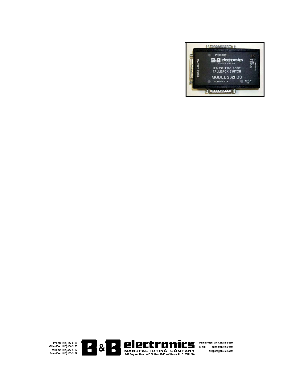
RS-232 Fallback Switch
Model 232FBC
Introduction
B&B Electronics' Model 232FBC permits two serial devices to share a
serial port on a host computer by automatically switching between the two. This
can be done through two different modes of automated switching: Port Combiner
mode and Fallback mode. In Port Combiner mode whichever port asserts control
first is enabled and locks out the other port until the first port drops control. In
Fallback mode the Primary port is enabled as the default port and you can select
whether the Primary or Alternate port overrides the other if both are transmitting.
The 232FBC can also be switched manually to either port using a toggle switch
located on the front of the device.
Asserting Control
Slave ports assert control in two ways. The first is to transmit data from one of the slave ports. This latches the
assertion for the duration of the transmission and 50 milliseconds after data has stopped. The second way to assert control
is to raise a jumper selected handshake line. The handshake line can be set independently on each slave port to CD, CTS,
or DSR. Use JP1 to select the controlling handshake line for the Primary port and JP4 to select the controlling handshake
line for the Alternate port. To disable the handshake control on either slave port, simply remove the corresponding jumper.
The path will not drop control until the selected handshake line has been lowered and data has ceased to transmit for 50
milliseconds.
When a slave port has asserted control that port is enabled. This allows data to flow freely between the master and
asserted ports. The 232FBC holds DTR high on a slave port when it is enabled or is capable of being enabled. This
indicates that the port is able to communicate with the master port. When it is not possible for a slave port to communicate
with the master port the 232FBC will lower DTR on that slave port.
Automatic Switching
Port Combiner Mode:
Use this mode when you have two devices of equal priority and you want to connect to
whichever is ready. Whichever port asserts control first is enabled and has its DTR held high. This locks out the other port
and holds its DTR low until the first port drops control. When neither port asserts control, both ports are disabled and have
DTR raised. To select this mode, set the toggle switch on the top to "Auto". Remove the screws in the box and remove the
cover to reveal the jumpers. Set the Mode jumper (JP2) to "Port Combiner". The Override jumper (JP3) has no effect.
Fallback Mode:
Use this mode for switching between redundant lines or for specific switching needs that are not
covered under Port Combiner mode. When neither port asserts control, the Primary port is enabled and DTR is raised on
both slave ports. When both slave ports attempt to assert control the 232FBC enables the port that is selected by the
override jumper (JP3), raising its DTR and lowering DTR on the other slave port. When one slave port asserts itself that port
is enabled and its DTR is raised. In this case DTR is lowered on the non-asserted slave port if it is NOT selected as the
override port. To select this mode, set the toggle switch on the top to "Auto". Remove the screws in the box and remove the
cover to reveal the jumpers. Set the Mode jumper (JP2) to "Fall Back", and set the Override jumper (JP3) to "Alternate" or
"Primary".
Manual Switching
On the top of the 232FBC there is toggle switch labeled "Primary Auto Alternate". This allows the user to manually
switch to the Primary or Alternate slave port without interfering with the jumper settings just like a switch box. Selecting
"Primary" or "Alternate" with the toggle switch overrides the automatic switching features and enables that slave port, raising
its DTR and lowering the other port's DTR.
Pinouts
The Master port on the 232FBC is configured as an RS-232 DCE port with a DB25 female connector. The Alternate
and Primary ports on the 232FBC are configured as RS-232 DTE ports with a DB25 male connector on each. Table 1 and
Table 2 show the configurations of the ports.
