 | –≠–ª–µ–∫—Ç—Ä–æ–Ω–Ω—ã–π –∫–æ–º–ø–æ–Ω–µ–Ω—Ç: 232FLST | –°–∫–∞—á–∞—Ç—å:  PDF PDF  ZIP ZIP |

Document No. 232FLST4300 ≠ pg. 1/3
© B&B Electronics ≠ Revised November 2000
This product designed and manufactured in USA of domestic and imported parts by
Port Powered RS-232 Fiber Optic Modem With Handshake Support
CE
CE
CE
CE
Model 232FLST
Description
The 232FLST allows any two pieces of RS-232 asynchronous serial
equipment to communicate full duplex over two multi-mode fibers. Typical distances
up to 2.5 miles (4 Km) are possible with no external power required. The 232FLST
supports both data signals at up to 115.2 Kbps as well as the RTS/CTS handshake
lines. This means the 232FLST can replace short haul modems and isolators when
connecting remote devices, while providing the EMI/RFI and transient immunity of
optical fiber.
RS-232 connections are provided on the same DB-25 female connector, while the multi-mode fiber is connected
via two ST connectors. The unit is port powered by the RS-232 Transmit Data and handshake lines. When handshake
lines are not available, or when using a low power RS-232 port, the 232FLST can be powered by an external 12VDC
supply, drawing 50 mA max.
RS-232 Connections
Connection of the 232FLST is simple and straightforward. The DB-25 female serial connector is used for
connecting the RS-232 data and handshake signals. The connector is pinned as a DCE device (input on Pin 2 and output
on Pin 3.) This means that a straight through cable can be used from your DB-25 port from any DTE device such as a PC
or terminal. A standard 9 to 25-pin adapter can be used in cases where the serial port on the DTE device is a DB-9. For
connecting to modems or other DCE devices, a null modem cable or adapter that swaps pins 2 & 3 is needed. Care
should be taken that any output handshake lines be connected through to the 232FLST to power the unit. See Figure 1
for connection diagrams to 9 pin and 25 pin DTE and DCE devices.
Figure 1: RS-232Connection Diagrams
D B 9 D T E D e v ic e
T D
R D
R T S
C T S
S ig n a l G N D
3
2
7
8
5
D B 9 D C E D ev ice
S ig n a l G N D
3
2
7
8
5
D B 2 5 D T E D e v ice
T D
R D
R T S
C T S
D T R
S ig n a l G N D
2
3
4
5
2 0
6
8
7
2
3
4
5
2 0
7
D B 2 5 D C E D ev ic e
T D
R D
R T S
C T S
D S R
D C D
S ig n a l G N D
3 (R D )
2 (T D )
5 (C T S )
4 (R T S )
2 0 (D T R )
7
o r
2 3 2 F L S T D B 2 5
2
3
4
5
6
8
7
2
3
4
5
7
2 3 2 F L S T D B 2 5
2 3 2 F L S T D B 2 5
2 3 2 F L S T D B 2 5
7
2 0
P O W E R
T D
R D
R T S
C T S
3 (R D )
2 (T D )
5 (C T S )
4 (R T S )
D S R
D C D
2 0 (D T R )
o r
P O W E R
P O W E R
1
6
4
1
6
4
D T R
2 0
P O W E R

Document No. 232FLST4300 ≠ pg. 2/3
© B&B Electronics ≠ Revised November 2000
This product designed and manufactured in USA of domestic and imported parts by
Fiber Optic Connections
The 232FLST uses a separate LED emitter and photo-detector operating at 820 nm wavelength. Connections to
the emitter and detector are on ST type connectors. Almost any multi-mode glass fiber size can be used including 50/125
µ
m, 62.5/125
µ
m, 100/140
µ
m, and 200
µ
m. Two fibers are required between the two modems, one for data in each
direction.
The most important consideration in planning the fiber optic link is the "power budget" of the fiber modem. This
value tells you the amount of loss in dB that can be present in the link between the two modems before the units fail to
perform properly. This value will include line attenuation as well as connector loss. For the 232FLST the typical
connector to connector power budget is 12.1 dB. Because 62.5/125
µ
m cable typically has a line attenuation of 3 dB per
Km at 820 nm, the 12.1 dB power budget translates into 2.5 miles (4 Km). This assumes no extra connectors or splices in
the link. Each extra connection would typically add 0.5 dB of loss, reducing the possible distance by 166 m (547 ft.) Your
actual loss should be measured before assuming distances. When the 232FLST is used without external power, the
power available to the Fiber Optic transmitter may be less than the typical value. The link should be tested with the
232FLST in place with a variable attenuator to check the optical power budget of the whole system.
Specifications
Transmission Line:
Dual multi-mode optical cable
Transmission Mode:
Asynchronous, half or full-duplex, point-to-point
Interface:
RS-232
Signals:
Transmit Data, Receive Data, Request to Send, Clear to Send
Data Rates:
0 to 115.2 K bps
Typical Range:
Up to 2.5 Miles (4 Km) on multi-mode glass fiber
Coupled Power Budget:
12.1 dB
Optic Wavelength:
820 nm
Connectors:
DB-25 Female for serial connection, ST Connectors for fiber
Power Supply:
Port Powered from Transmit Data, RTS, and DTR lines
Optional External Power Supply:
10 ≠ 16 VDC @ 50 mA max.
Dimensions:
4.3"L x 2.3"W x 0.95"H (10.9 x 5.8 x 2.4 cm)
Figure 2: Typical Setup
T X
R X
2 32 F LS T
R X
T X
2 3 2 F L S T
R S -2 3 2
D E V IC E
D up le x
M u ltim o d e
F ib e r
R S -2 3 2
D E V IC E
Document No. 232FLST4300 ≠ pg. 3/3
© B&B Electronics ≠ Revised November 2000
This product designed and manufactured in USA of domestic and imported parts by
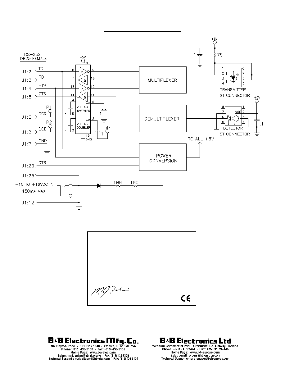
Figure 3: 232FLST Circuit Diagram
DECLARATION OF CONFORMITY
Manufacturer's Name:
B&B Electronics Manufacturing Company
Manufacturer's Address:
P.O. Box 1040
707 Dayton Road
Ottawa, IL 61350 USA
Model Numbers:
232FLST
Description:
Port-Powered Fiber Optic Modem
Type:
Light industrial ITE equipment
Application of Council Directive: 89/336/EEC
Standards:
EN 50082-1 (IEC 801-2, IEC 801-3, IEC 801-4)
EN 50081-1 (EN 55022, IEC 1000-4-2)
EN 61000 (-4-2, -4-3, -4-4, -4-5, -4-6, -4-8, -4-11)
ENV 50204
EN 55024
Michael J. Fahrion, Director of Engineering