Document No. 485LP9R4500 - pg. 1/2
© B&B Electronics -- Revised November 2000
This product designed and manufactured in USA of domestic and imported parts by
Port Powered RS-232 to RS-485 Converter
CE
Model 485LP9R
The 485LP9R is a port-powered two-channel RS-232 to RS-485 converter. It
converts TD and RD RS-232 lines to balanced RS-485 signals. The unit can be
powered from the RS-232 handshake lines, DTR and RTS. One of these
handshakes must be high (asserted) to power the unit (See Table 1). DTR must
be asserted to receive data. The RS-485 driver is enabled when RTS is asserted
and disabled when RTS is disasserted. The RS-485 receiver is disabled when
the driver is enabled and is enabled when the driver is disabled.
In order to maximize the amount of power available to the RS-485 driver, the
RS-232 handshake lines are not looped back (tied together). As a result the following handshake lines will appear as
disasserted (low): CTS, DCD, and DSR. Care should be taken to insure that any software being used doesn't require any
of these handshake lines be asserted. If existing software requires any of the handshake lines to be asserted, you can
loop back the required handshake lines in your cable.
Table 1
* NOTE: Low = disasserted and High = asserted
Connections
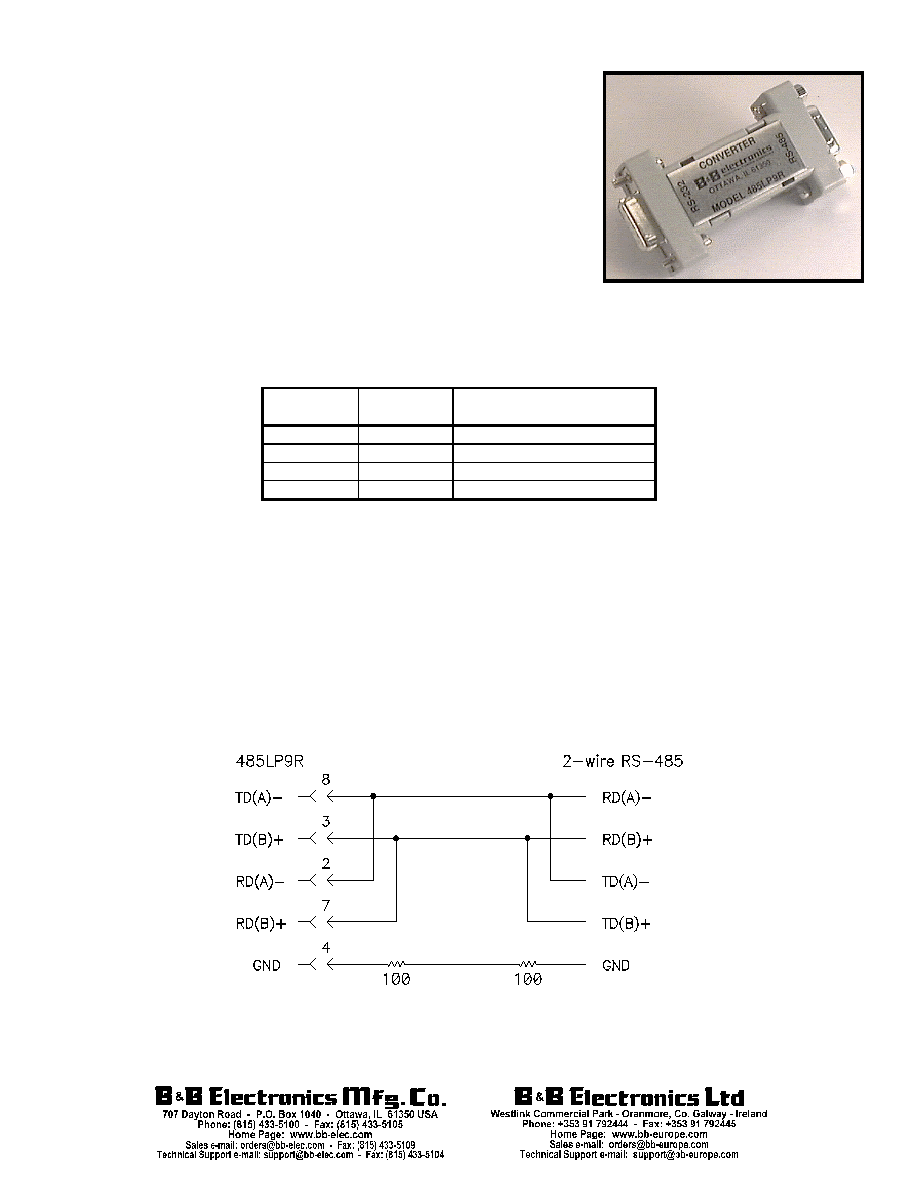
A typical two wire RS-485 connected is shown in Figure 1. Regardless of the system, the 485LP9R must be
connected with the proper polarity. With no data is being sent and the driver enabled, the RS-232 line should be negative
and the TD(A) should be negative with respect to TD(B).
Proper operation of any RS-485 system requires the presence of a signal return path between the signal grounds of
the equipment at each end of an interconnection. This circuit reference may be established by a third conductor
connecting the common leads of devices, or it may be provided by connections in each equipment to an earth reference.
When the circuit reference is provided by a third conductor, the connection between the signal grounds and the third
conductor should contain some resistance (e.g. 100 ohms) to limit circulating currents when other ground connections are
provided for safety.
Figure 1
RTS State
DTR State
Functions Possible
(when port powering unit)
Low
Low
none
Low
High
Receive
High
Low
Transmit
High
High
Transmit

Document No. 485LP9R4500 - pg. 2/2
© B&B Electronics -- Revised November 2000
This product designed and manufactured in USA of domestic and imported parts by
Table 2 - 485LP9R Pin Outs
Biasing Resistors
The biasing resistors for the RS-485 receiver are 4.7K Ohm resistors. These resistors are labeled R1 and R6 (See
Figure 2). Refer to B&B Electronics RS-422/485 Application Note for further information on biasing.
Figure 2
Specifications
Data Rate:
115.2K Baud max.
Power: Port Powered from RTS and DTR.
Note: If external power is required, apply power to DTR (4) and SG (5). Source must supply greater than 6VDC
and current limited to 40mA
NOTE: When using an external supply, the supply should be connected only to specifically labeled power inputs
(power jack, terminal block, etc.). Connecting an external power supply to the handshake lines may damage the
unit. Contact technical support for more information on connecting an external power supply to the handshake
lines.
Signal
DB-9S Pin #
Transmit Data A (-)
8
Transmit Data B (+)
3
Receive Data A (-)
2
Receive Data B (+)
7
Signal Ground
4, 6
DECLARATION OF CONFORMITY
Manufacturer's Name:
B&B Electronics Manufacturing Company
Manufacturer's Address:
P.O. Box 1040
707 Dayton Road
Ottawa, IL 61350 USA
Model Number:
485LP9R
Description:
9-Pin Port-Powered RS-485 Converter
Type:
Light industrial ITE equipment
Application of Council Directive:
89/336/EEC
Standards:
EN 50082-1 (IEC 801-2, IEC 801-3, IEC 801-4)
EN 50081-1 (EN 55022, IEC 1000-4-2)
EN 61000 (-4-2, -4-3, -4-4, -4-5, -4-6, -4-8, -4-11)
ENV 50204
EN 55024
Michael J. Fahrion, Director of Engineering