
ADJUSTABLE PRECISION SHUNT REGULATORS AS431
Data Sheet
1
Nov. 2005 Rev. 1. 1
BCD Semiconductor Manufacturing Limited
General Description
The AS431 series ICs are three-terminal adjustable
shunt regulators with guaranteed thermal stability over
a full operation range. These ICs feature sharp turn-on
characteristics, low temperature coefficient and low
output impedance, which make them ideal substitutes
for Zener diodes in applications such as switching
power supply, charger and other adjustable regulators.
The output voltage of these ICs can be set to any value
between V
REF
(2.5V) and the maximum cathode volt-
age (36V).
The AS431 precision reference is offered in two band-
gap tolerance: 0.4% and 0.8%.
These ICs are available in 4 Packages: TO-92, SOT-23-
3, SOT-23-5 and SOT-89 .
Features
∑
Programmable Precise Output Voltage from 2.5V
to 36V
∑
Very Accurate Reference Voltage: 0.15% Typical
∑
High Stability under Capacitive Load
∑
Low Temperature Deviation: 4.5mV Typical
∑
Low Equivalent Full-range Temperature Coeffi-
cient with 20PPM/
o
C Typical
∑
Low Dynamic Output Resistance: 0.15
Typical
∑
Sink Current Capacity from 1mA to 100 mA
∑
Low Output Noise
∑
Wide Operating Range of -40 to 125
o
C
Applications
∑
Charger
∑
Voltage Adapter
∑
Switching Power Supply
∑
Graphic Card
∑
Precision Voltage Reference
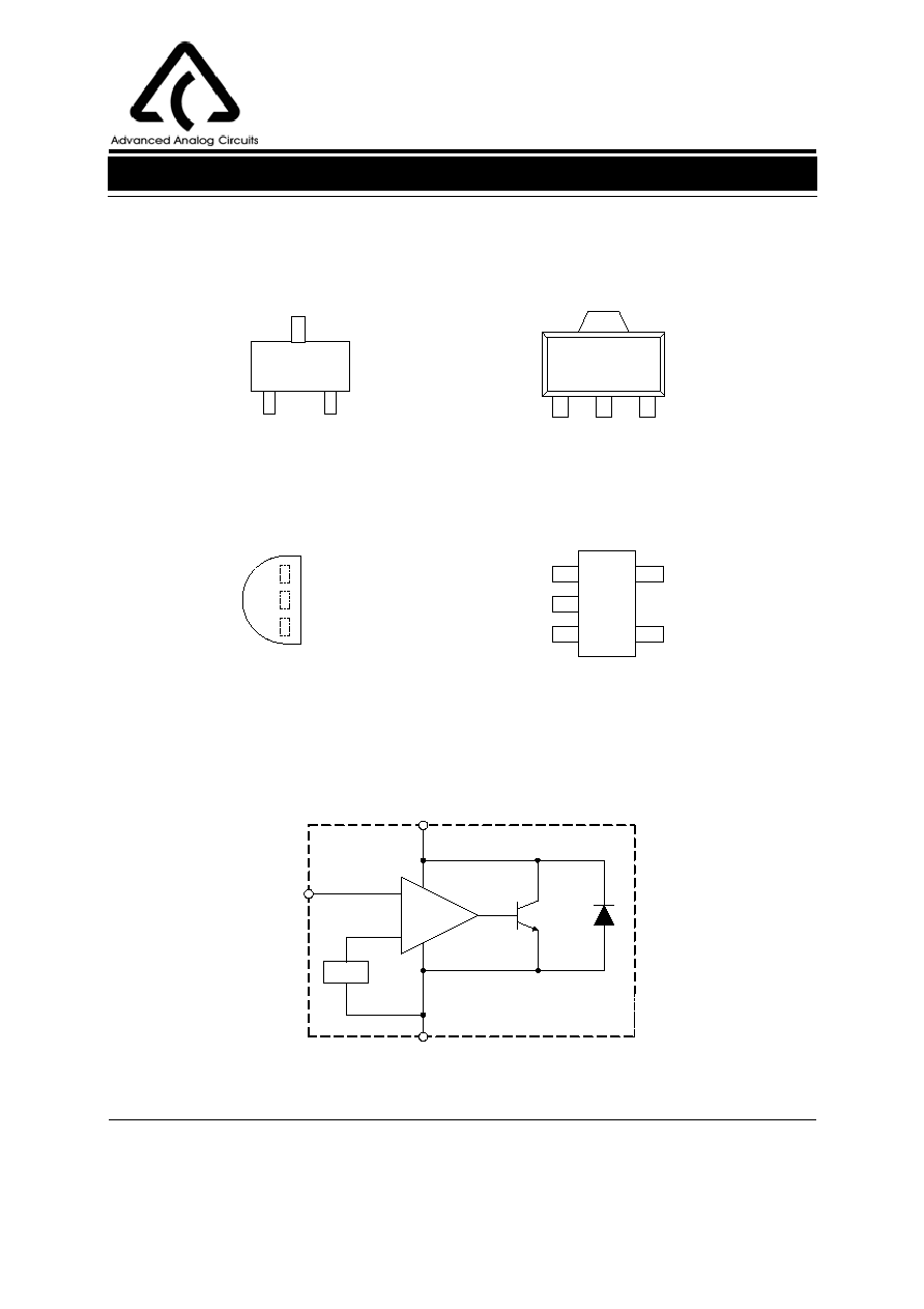
SOT-23-3
TO-92
SOT-89
Figure 1. Package Types of AS431
SOT-23-5
ADJUSTABLE PRECISION SHUNT REGULATORS AS431
Data Sheet
2
Nov. 2005 Rev. 1. 1
BCD Semiconductor Manufacturing Limited
Figure 2. Pin Configuration of AS431 (Top View)
Z Package
(TO-92)
(SOT-23-3)
N Package
R Package
(SOT-89)
Figure 3. Functional Block Diagram of AS431
Functional Block Diagram
ANODE
REF
REF ANODE
1
2
3
1
2
3
K Package
(SOT-23-5)
NC
ANODE
REF
3
2
1
4
5
NC
REF
V
REF
CATHODE
ANODE
+
-
CATHODE
ANODE
REF
1
2
3
Pin Configuration
CATHODE
CATHODE
CATHODE

ADJUSTABLE PRECISION SHUNT REGULATORS AS431
Data Sheet
3
Nov. 2005 Rev. 1. 1
BCD Semiconductor Manufacturing Limited
Ordering Information
Circuit Type
Bandage Tolerance
B: 0.8%
A: 0.4%
E1: Lead-Free
Blank: Tin Lead
AS431 -
Package
Temperature
Range
Voltage
Tolerance
Part Number
Marking ID
Packing
Type
Tin Lead
Lead Free
Tin Lead
Lead Free
SOT-23-3
-40 to
125
o
C
0.4%
AS431ANTR-E1
EB5
Tape & Reel
0.8%
AS431BNTR-E1
EB6
Tape & Reel
SOT-23-5
-40 to
125
o
C
0.4%
AS431AKTR-E1
E6H
Tape & Reel
0.8%
AS431BKTR-E1
E6I
Tape & Reel
TO-92
-40 to
125
o
C
0.4%
AS431AZ-E1
AS431AZ-E1
Bulk
0.4%
AS431AZTR-E1
AS431AZ-E1
Ammo
0.8%
AS431BZ-E1
AS431BZ-E1
Bulk
0.8%
AS431BZTR-E1
AS431BZ-E1
Ammo
SOT-89
-40 to
125
o
C
0.4%
AS431ARTR-E1
E43G
Tape & Reel
0.8%
AS431BRTR-E1
E43H
Tape & Reel
Package
N: SOT-23-3 K: SOT-23-5
R: SOT-89
TR: Tape and Reel or Ammo
Blank: Tube or Bulk
BCD Semiconductor's Pb-free products, as designated with "E1" suffix in the part number, are RoHS compliant.
Z: TO-92

ADJUSTABLE PRECISION SHUNT REGULATORS AS431
Data Sheet
4
Nov. 2005 Rev. 1. 1
BCD Semiconductor Manufacturing Limited
Parameter
Symbol
Value
Unit
Cathode Voltage
V
KA
40
V
Cathode Current Range (Continuous)
I
KA
-100 to 150
mA
Reference Input Current Range
I
REF
10
mA
Power Dissipation
P
D
Z, R Package: 770
mW
N, K Package: 370
Junction Temperature
T
J
160
o
C
Storage Temperature Range
T
STG
-65 to 150
o
C
Package Thermal Impedance
JA
N Package: 330
o
C/W
Z Package: 150
R Package: 50
K Package: 250
ESD (Human Body Model)
4000
V
Parameter
Symbol
Min
Max
Unit
Cathode Voltage
V
KA
V
REF
36
V
Cathode Current
I
KA
1.0 100
mA
Operating Ambient Temperature Range
-40
125
o
C
Recommended Operating Conditions
Note 1: Stresses greater than those listed under "Absolute Maximum Ratings" may cause permanent damage to the
device. These are stress ratings only, and functional operation of the device at these or any other conditions beyond
those indicated under "Recommended Operating Conditions" is not implied. Exposure to "Absolute Maximum
Ratings" for extended periods may affect device reliability.
Absolute Maximum Ratings (Note 1)

ADJUSTABLE PRECISION SHUNT REGULATORS AS431
5
Nov. 2005 Rev. 1. 1
BCD Semiconductor Manufacturing Limited
Data Sheet
Parameter
Test
Circuit
Symbol
Conditions
AS431
Unit
Min
Typ
Max
Reference Voltage
0.4%
4
V
REF
V
KA
=V
REF,
I
KA
=10mA
2.490
2.500
2.510
V
0.8%
2.480
2.500
2.520
Deviation of Reference
Voltage Over-temperature
4
V
REF
V
KA
=V
REF
I
KA
=10mA
0 to 70
o
C
4.5
8
mV
-40 to 85
o
C
4.5
10
Ratio of Change in Reference
Voltage to the Change in
Cathode Voltage
5
V
REF
V
KA
I
KA
=10mA
V
KA
=
10V to V
REF
-1.0
-2.7
mV/V
V
KA
=
36V to 10V
-0.5
-2.0
Reference Current
5
I
REF
I
KA
=10mA, R1=10K
, R2=
0.7
4
µA
Deviation of Reference Current
Over Full Temperature Range
5
I
REF
I
KA
=10mA, R1=10K
R2=
, T
A
=-40 to 85
o
C
0.4
1.2
µA
Minimum Cathode Current for
Regulation
4
I
KA
(Min)
V
KA
=V
REF
0.4
1.0
mA
Off-state Cathode Current
6
I
KA
(Off)
V
KA
=36V, V
REF
=0
0.05
1.0
µA
Dynamic Impedance
4
Z
KA
V
KA
=V
REF
, I
KA
=1 to 100mA,
f
1.0KHz
0.15
0.5
Electrical Characteristics for AS431
Operating Conditions: T
A
=25
o
C, unless otherwise specified.