4
4-161
Models 898, 899
ELECTRICAL
Standard Resistance Range, Ohms *
10 to 10Meg
Standard Resistance Tolerance, at 25įC
Ī2% (<33 Ohms = Ī2 Ohms)
Optional: Ī1% (F Tol.)
Operating Temperature Range
-55įC to +125įC
Temperature Coefficient of Resistance
Ī100ppm/įC (<100 Ohms = Ī250ppm/įC)
Temperature Coefficient of Resistance Tracking
Ī50ppm/įC
Maximum Operating Voltage
100Vdc or
PR
Insulation Resistance
10,000 Megohms
ENVIRONMENTAL (PER MIL-R-83401)
Thermal Shock plus Power Conditioning
R 0.70%
Short Time Overload
R 0.50%
Terminal Strength
R 0.25%
Moisture Resistance
R 0.50%
Mechanical Shock
R 0.25%
Vibration
R 0.25%
Low Temperature Storage
R 0.25%
High Temperature Exposure
R 0.50%
Load Life, 1,000 Hours
R 1.00%
Resistance to Solder Heat (Per MIL-STD-202, Method 210, Cond.B)
R 0.25%
Dielectric Withstanding Voltage
200V rms for 1 minute
Temperature Exposure, Maximum
215įC for 3 minutes
Marking Permanency
MIL-STD-202, Method 215
Lead Solderability
MIL-STD-202, Method 208
Flammability
UL-94V-O Rated
Storage Temperature Range
-55įC to +125įC
* Plus "0 Ohm" jumper
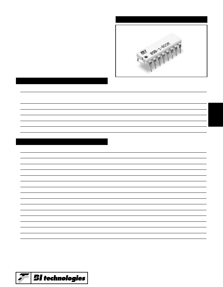
MODELS 898, 899
Dual-In-Line
Thick Film
Resistor Networks
Specifications subject to change without notice.

----Resistor (Per Circuit)----
Model
Package -1
-3
-5
898
2.0
.125
.250
.125
899
1.8
.125
.250
.125
POWER DISSIPATION, WATTS AT 70įC
4-162
Models 898, 899
Lead Material
Copper Alloy, 60/40 Tin-Lead (Plating)
Substrate Material
Alumina
Resistor Material
Cermet
APPLICABLE DOCUMENTS
MIL-R-83401 -- Resistor Networks, Fixed, Film, General Specifications
MIL-STD-105 -- Sampling Procedures and Tables for Inspection by Attributes
MIL-STD-202 -- Test Methods for Electronic and Electrical Component Parts
22
390
5.6K
100K
27
470
6.8K
120K
33
510
8.2K
150K
39
560
10K
180K
47
680
12K
200K
51
820
15K
220K
56
1K
18K
270K
68
1.2K
20K
330K
82
1.5K
22K
390K
100
1.8K
27K
470K
120
2K
33K
510K
150
2.2K
39K
560K
180
2.7K
47K
680K
200
3.3K
51K
820K
220
3.9K
56K
1Meg
270
4.7K
68K
330
5.1K
82K
R1/R2
R1/R2
R1/R2
R1/R2
180/390
220/330
330/470
3K/6.2K
220/270
330/390
330/680
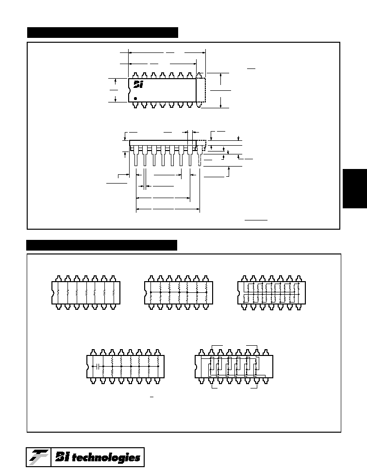
-5 Circuit (Dual Terminators)
-3 Circuit (Isolated Resistors) & -1 Circuits (Bussed Resistors)
MECHANICAL
STANDARD RESISTANCE VALUES, OHMS
4
4-163
Models 898, 899
N
1
N/2
-3 Circuit - Isolated Resistors
-1 Circuit - Bussed Resistors
N
1
N/2
-5 Circuit - Dual Terminator
N
R1
R2
1
N/2
-42 Circuit - 5.2V (VEE) Pull-Down
VCC
VCC
VEE
1
16
c
R
R
R
R
R
R
R
R
R
R
R
R
VEE
-45 Circuit - TTL to ECL Translator
VCC
VCC
R1
180
270
820
R2
R3
1
16
TTL Inputs
Outputs To ECL
Custom Model: 898-45
R1=180
R2=270
R3=820
Custom Model: 898-42-R (R)
R=510
VEE
SCHEMATICS
Max.
Notes:
Unless otherwise specified,
tolerances are
Ref.
.050
1.27
Max.
.125
3.18
Ref.
.060
1.52
Max.
.185
4.70
Min.
.020
0.51
Max.
.880
22.4
Model 898
Model 899
Max.
.780
19.8
Ī
.005
0.13
Ref.
.250
6.35
.135
Ī
.030
3.43
Ī
0.76
Typical spacing
non-accumulating
lead thickness:
*
.010
Ī
.002
0.25
Ī
0.05
.340
Ī
.020
8.64
Ī
0.51
.600
Ī
.010
15.2
Ī
0.25
.018
Ī
.003
0.46
Ī
0.08
.100
Ī
.010*
2.54
Ī
0.25
.080
Ī
.020
2.03
Ī
0.51
.700
Ī
.010
17.8
Ī
0.25
OUTLINE DIMENSIONS (Inch/mm)
Note: Model 899: N = 114 Leads, Model 898: N = 16 Leads.
Custom circuits are available. Consult Factory.
4-164
Models 898, 899
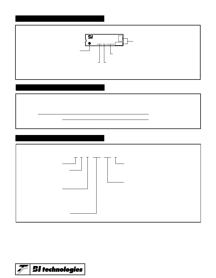
89 9 -5- R220 / R330 F
Model Series
Tolerance Code:
F =
Ī
1%
(No code used for standard tolerances.)
R2 Resistance Value:
(Add for -5 circuit only)
Number of Leads:
9 = 14 Leads
8 = 16 Leads
Circuit Type:
3 = Isolated
1 = Bussed
5 = Dual Terminator
Resistance Value
ORDERING INFORMATION
PACKAGING
Standard: Magazines
All Units oriented with lead #1 to the same side.
Magazine:
Material
=
Antistatic Plastic
Capacity
=
25 Units
898-3-R10K
Package Code ≠ # Of Leads
899 = 14 Leads
898 = 16 Leads
Lead #1
Indicator
Resistance Value
Date Code
Optional Locations
Circuit Type: (≠1 Bussed)
(≠3 Isolated)
(≠5 Dual Terminator)
TYPICAL PART MARKING