Data
sheet
www.bookham.com
Thinking optical solutions
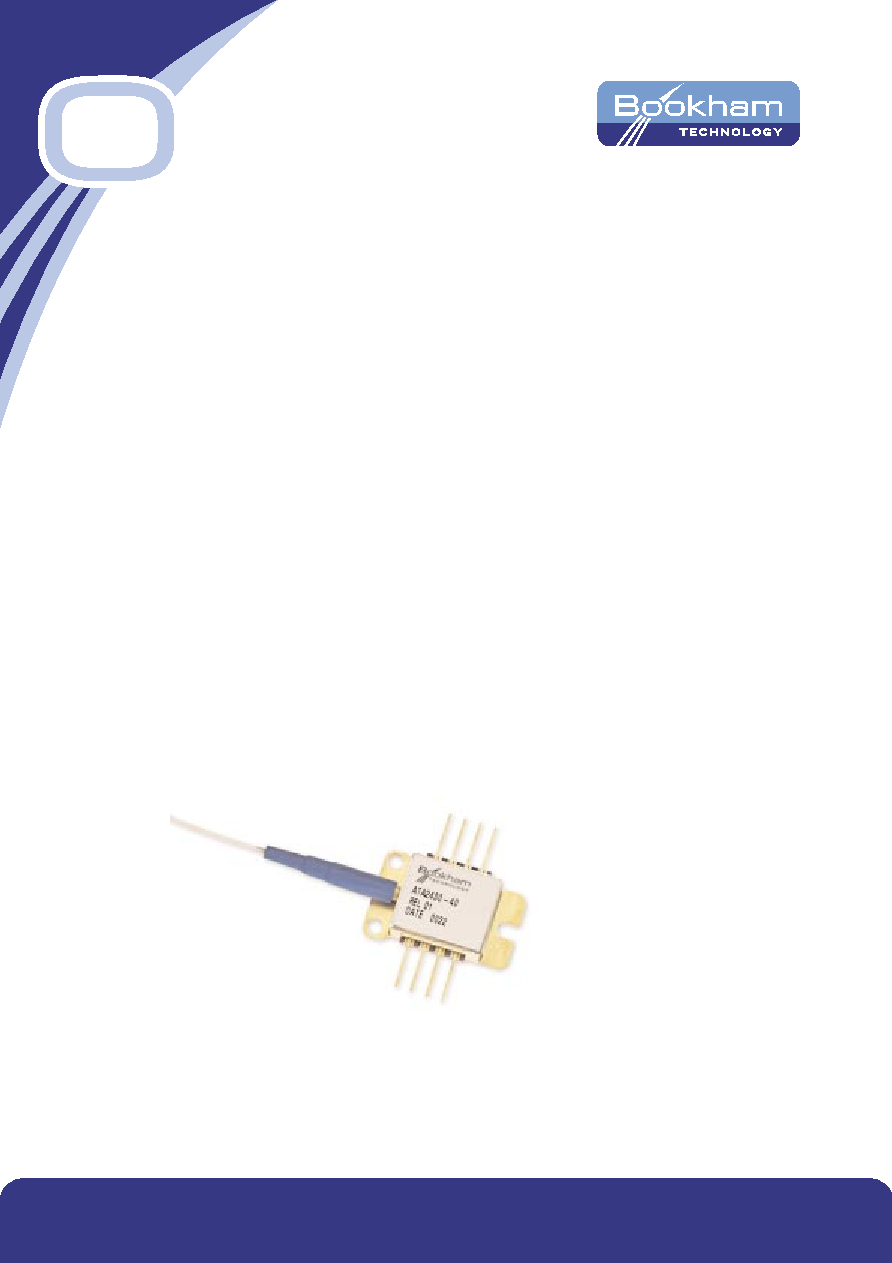
2.5 Gb/s APD
Preamp Receiver -
uncooled
The 2.5 Gb/s APD Preamp Receiver - uncooled comprises
a high speed APD coupled to a non-inverting HBT
transimpedance amplifier with a style-ended output.
The receiver is housed in an 8 pin butterfly package with
a single mode fibre pigtail. The integral thermistor may be
used in an active bias control loop to compensate for
ambient temperature variation.
www.bookham.com
Thinking optical solutions
Features
∑ High sensitivity -34 dBm
∑ High dynamic range
∑ High bandwidth
∑ Integrated thermistor
∑ Integrated non-inverting
preamplifier
∑ Single product code covers full C
and extended L-band operation
Applications
∑ Long reach STM16/OC48
receivers

Parameter
Symbol
Min
Typ
Max
Unit
Conditions
Module responsivity
R-15
0.75
0.92
A/W
1550 nm, M = 1
R-13
0.70
0.88
A/W
1310 nm, M = 1
Module breakdown voltage
Vbr
40
52
60
V
Ir = 10 µA
Temperature coef of Vbr
þ
0.12
V/∞C
þ = dVbr/dTc
Transimpedance
Zt
1.7
k
DC-coupled, RL = 50
Bandwidth (-3 dB)
BW
1.8
2.4
3.2
GHz
AC-coupled, RL = 50
,
M = 10
Sensitivity
Pr
-34
-32.5
dBm
2.5 Gb/s,
PRBS = 2 ^(23)-1
NRZ, BER = 10 ^(-10)
Vr = optimum Vbias
Output amplitude
Vout
12
2000
mVpp
max. value at -8 dBm,
M = 3
min. value at -34 dBm,
M = 10
Overload power
Pol
-7
-5
dBm
M=3
Optical return loss
Prtn
30
dB
Power supply voltage
Vcc
5
V
Vr
10
65
V
APD bias
Power supply current
Icc
69
80
mA
Thermistor resistance
Rth
9.5
10
10.5
K
Characteristics
(Tcase = 25∞C, Wavelength = 1550 nm, Vcc = 5 V unless otherwise stated)
Parameter
Symbol
Min
Typ
Max
Unit
Conditions
Operating case temp.
Top
-20
70
∞C
Storage temp.
Tstg
-40
85
∞C
Supply voltage
Vcc
0
6
V
APD reverse voltage
Vr
0
Vbr
V
Breakdown voltage (Vbr)
varies from device to
device. Vbr value supplied
with each device
APD reverse current
Ir
2
mA
Lead soldering temperature
-
250
∞C
Lead soldering time
-
10
s
Absolute Ratings
These limits are absolute stress levels only, functional operation of the device is not guaranteed at these levels.
Long-term exposure to these limits could result in reduced reliability of the device.
(Tcase = 25∞C unless otherwise stated)
www.bookham.com
Thinking optical solutions
www.bookham.com
Thinking optical solutions
Instructions for Use
Pin 1 APD Bias (+)
DC bias voltage for the APD. During power-up, in order to
prevent forward-biasing the APD, this bias voltage should
be applied before the pre-amp power (PIN 3) is applied.
The maximum mean current is O.5 mA. The bias voltage
will normally be controlled externally to optimise the
operating point. This voltage will typically range from 10 V
to 65 V.
Pin 2, 7, 5 Ground
Ground all pins for optimum performance.
Pin 3 Vcc (+)
Positive supply voltage between 4.75 V and 5.25 V to be
applied after the APD bias voltage is present. The supply
should be filtered to minimise noise ingress and be
capable of delivering up to 80 mA.
Pin 4 Nc
No connection on this pin.
Pin 6 Output
The RF output has a DC offset typically between 1.9 V
and 3.0 V, so may be AC coupled into 50 W load.
Maximum output is 2 Vpp.
Pin 8 Thermistor
The negative temp coefficient thermistor may be used in a
control loop to optimise the bias voltage according to
device temperature. The thermistor has a nominal
resistance of 10 kW at 25∞C, and is not polarity sensitive
although one side is connected to package ground.
Operating current should be limited to 100 µA to prevent
self-heating errors.
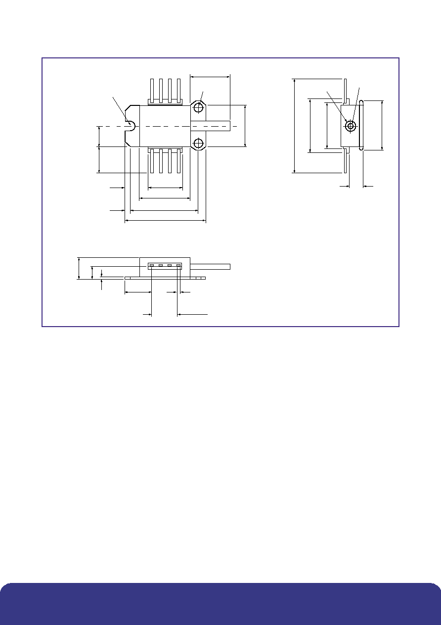
11
.
2
12.9
15
15.4
30
8.55
6.5
4.4
0.8
6.45
7.94
8 x 0.5
3.4
3 x 2.54 = 7.62
10
10.2
¯2.5
¯1.7
R 1.2
2 X ¯2.4
15
20
2
7
24
Outline Drawing
Dimensions in mm
www.bookham.com
Thinking optical solutions
www.bookham.com
Thinking optical solutions
Certificate No. FM 15040
Certificate No. EMS 35100
CAUTION
STATIC SENSITIVE DEVICE
OBSERVE PRECAUTIONS
Ordering Information
Order Code No. ATA2400-40C**
Connector types: SC/PC = C28, fibre length 975-1035 mm
FC/PC = C33, fibre length 975-1035 mm
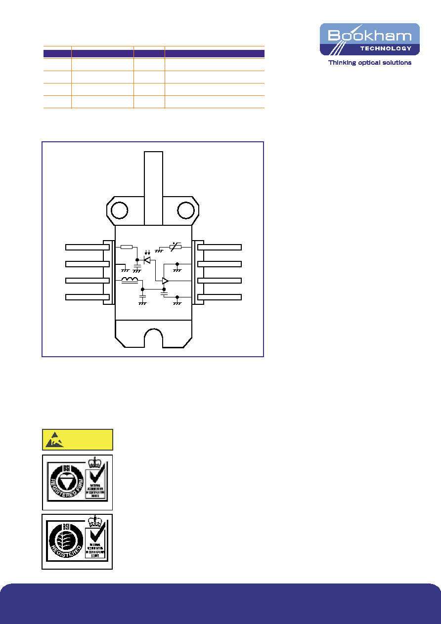
Pin #
Name
Pin #
Name
1
APD bias (+)
5
Ground
2
Ground
6
Output (DC coupled)
3
Power supply Vcc (+)
7
Ground
4
Not connected
8
Thermistor
Connections
Connector types: SC/PC = C28, fibre length 975 -1035 mm
FC/PC = C33, fibre length 975 -1035 mm
10 k
@ 25
o
C
8
7
6
5
1
2
3
4
www.bookham.com
REV 1 Feb 2003
© Bookham Technology 2003 Bookham & ASOC are registered trademarks of Bookham Technology plc
North America
Bookham Technology Inc.
49 Buford Highway
Suwanee
GA 30024
USA
∑ Tel: +1 678 482 4021
∑ Fax: +1 678 482 4022
Europe
Bookham Technology plc
Brixham Road
Paignton
Devon
TQ4 7BE
UK
∑ Tel: +44 (0) 1803 66 2875
∑ Fax: +44 (0) 1803 66 2801
Asia
Bookham Technology plc
21/F Cityplaza One
1111 King's Road
Quarry Bay
Hong Kong
∑ Tel: +852 (2100) 2249
∑ Fax: +852 (2100) 2585
Sales@bookham.com
Important Notice
Bookham Technology has a policy of
continuous improvement, as a result
certain parameters detailed on this flyer
may be subject to change without notice.
If you are interested in a particular product
please request the available from any
Bookham Technology sales representative.