
Data
sheet
www.bookham.com
Thinking optical solutions
10 Gb/s InP Mach
Zehnder Modulator
with DWDM Laser
The 10 Gb/s InP Mach Zehnder Modulator with DWDM Laser,
containing the Bookham Technology Strained Layer MQW DFB
laser chip and the InP Mach-Zehnder modulator chip, has been
designed specifically for use in 10 Gb/s long distance optical
fibre trunk systems. Thermo-electric heatpumps, a precision
NTC thermistor and optical isolator are incorporated. By using
the rear back facet monitors, the integrated Etalon locker
allows wavelength locking to the 50 GHz ITU grid. The module
is capable of >80 km transmission over Non Dispersion-Shifted
Fibre (NDSF) without additional dispersion compensation.
This is achieved by the negative chirp characteristic,
which compensates for 1500 ps/nm dispersion. Increased
transmission distances are possible using multiple spans of
NDSF with dispersion compensation. Optical power control
is achieved by applying a D.C. bias voltage to the internal
attenuator electrode. This reduces the power into the modulator
section without affecting the operating wavelength.
www.bookham.com
Thinking optical solutions
Features
∑ Voltage programmable output
power control
∑ Long haul performance with
negligible penalty
∑ Integral Etalon wavelength
stabilisation to within ± 20 pm
over life
∑ Differential or single 50 Ohm low
voltage drive modulation input
∑ Integral thermo-electric cooler
with precision NTC thermistor
for temperature control
∑ Hermetically sealed butterfly style
package with SMA RF
connectors
∑ ITU Wavelengths available from
1527 nm to 1608 nm
∑ 50 GHz channel spacing
Applications
∑ Long reach SONET/SDH
OC192/STM64 DWDM systems
to 50 GHz channel spacing

Parameter
Conditions
Min
Typ
Max
Unit
Modulated Output Power
(1)
50% duty cycle at T
case
= 25∞C
0
3.5
dBm
Modulated Output Power
(2)
- 12.0
Threshold current (l
th
)
40
mA
Slope efficiency
3.7
6
µ
W/mA
RF input reflection coeff. (S
11
)
to 8 GHz
10
dB
Laser Forward voltage
2.8
V
Peak wavelength
ITU Grid
1527.22
1608.33
nm
Wavelength Accuracy
SOL, ITU Grid
-37
+37
pm
Sidemode suppression ratio
40
dB
Optical rise/fall time
(20% - 80%)
50
ps
Monitor photocurrent
@ locked
0.15
mA
Monitor dark current
100
nA
Thermistor resistance
@ locked
6.81
10.09
k
Heatpump current
T
case
0-70
∞
C
1.8
A
Heatpump voltage
T
case
0-70
∞
C
5
V
M ≠ Z bias voltage (left arm)
@<12 mA
-4
-2
-1.1
V
M ≠ Z bias voltage (right arm)
@<12 mA
-5
0
V
Modulation voltage (single ended)
a.c. p-p
2.8
4
5.5
V
Extinction ratio
ac
13
dB
Attenuator voltage (0 ≠ 15 dB)
@ <30 mA
-8
0.5
V
Dispersion penalty
1500 ps/nm
1
dB
Characteristics
Conditions unless otherwise stated:
Submount temperature
30
∞
C ± 5
∞
C (for locked
)
Monitor diode bias
-5 V
(1) Start of life, power adjustment set for maximum output power
(2) Start of life, power adjustment set to -8.0 V
Absolute Ratings
Parameter
Conditions
Min
Typ
Max
Unit
Operating temperature
0
70
∞
C
Storage temperature
-40
85
∞
C
Laser forward current
275
mA
Laser reverse voltage
2
V
Monitor diode bias
15
V
TE cooler current
1.8
A
Mach-Zehnder bias voltage
-6
0.5
V
Attenuator voltage
-7.3
0.5
V
Fibre bend radius
30
mm
www.bookham.com
Thinking optical solutions
www.bookham.com
Thinking optical solutions

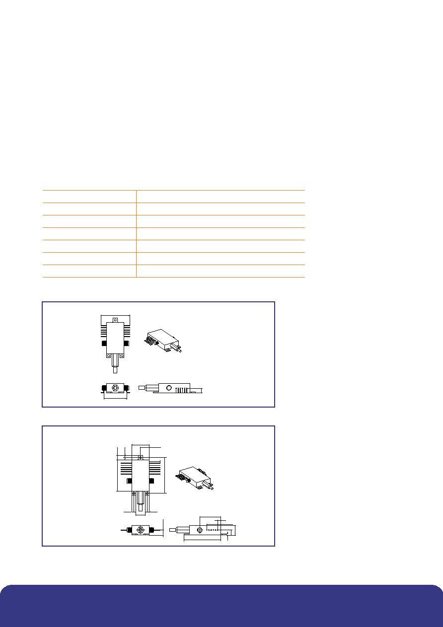
Outline Drawing
Dimensions in mm
47.00
1.50
6.00
11.20
6.3
10.50
21.00
2.50
42.00
16.00
2.50
1
25.00
37.00
68.00
6
7
12
L
R
¯0.5
4.00
THREE OFF HOLES ¯3 THROUGH.
C34
12.70 MIN
2.54 TYP
Instructions for Use
Pin 1 Ground
Package ground pin.
Pin 2 MZ Bias Left and Pin 11 MZ Bias Right
DC bias voltages for left and right MZ arms. These pins
must be connected to a negative DC voltage (typically
around -2 V) which is defined in the deliverable data.
The bias voltage source must be capable of delivering up
to 10 mA to each pin.
Pin 3 TEC (-) and Pin 4 TEC (+)
The package contains two peltier heatpumps connected
in series. Applying a negative voltage on Pin 3 with
respect to Pin 4 will cause the internal optics to be cooled
relative to the case temperature. Reversing the applied
voltage will cause the internal structures to be heated.
The power supply for the heatpumps should be capable
of sourcing up to 2 A at 5 V.
Pin 5 Thermistor
The thermistor is used in the control loop for keeping the
internal temperature at a constant value. It has a nominal
resistance of 8.2 k
at the typical operating temperature
of 30
∞
C and is not polarity sensitive, although one side
of the thermistor is connected to package ground.
Operating current should be limited to less than 100 µA
to prevent self-heating errors. The exact thermistor
value will be supplied with the LCM155EW variant
to ensure correct operating wavelength.
Pin 6 Monitor Anode (short), Pin 7 Monitor Anode
(long) and Pin 8 Monitor Cathode
The two back facet monitor diodes are used in a control
loop, which maintains constant laser wavelength.
Each diode has a different spectral response, which
overlaps at the "locked" wavelength. The loop can control
submount temperature and laser bias to maintain the two
monitor diode currents at equal values. The diodes are
operated with a reverse 5 V bias.
Pin 9 Laser Anode and Pin 10 Laser Cathode
The laser is operated with a forward bias current up
to 275 mA at 2.8 V. Threshold current is typically 30 mA
at 30
∞
C.
Figure 1: Outline Drawing
www.bookham.com
Thinking optical solutions
www.bookham.com
Thinking optical solutions
Pin 12 Attenuator
A negative DC voltage in the range 0 V to -8.0 V applied to this pin will attenuate the output power by up to 15.5 dB.
The supply should be capable of sinking up to 30 mA from this pin.
MZ Data Left
Single-ended data input with typical amplitude of 4.0 Vpp is applied via the SMA connector (the required value for optimum
performance is supplied with the device). Input must include a DC block.
MZ Data Right
When operating the module with a differential input, data is applied to both left and right arms. Typical amplitude is 2.0 Vpp
in this mode. Again, a DC block is necessary. This input should be terminated with a 50
DC load if operating with a
single ended input on the left arm.
Package Pinout
SMA
MZ Left Data
SMA
MZ Right Data
Pin 1
Ground
Pin 12
Attenuator
2
MZ Bias Left
11
MZ Bias Right
3
TEC (-)
10
Laser Cathode
4
TEC (+)
9
Laser Anode
5
Thermistor
8
Monitor Cathodes
6
Monitor Anode (short)
7
Monitor 2 Anode (long)
34
27 pitch
6
GULLWING
-64
Figure 2: Gullwing-64
21
25
47
5 x 2.54
4
11
2.5
2.5
37
42
10.5
12.7
6
1.5
11.2
STRAIGHT -65
2.5
5
6.3
Figure 3: Straight-65
www.bookham.com
Thinking optical solutions
www.bookham.com
Thinking optical solutions

CLASS 1 LASER PRODUCT
Certificate No. FM 15040
Certificate No. EMS 35100
CAUTION
STATIC SENSITIVE DEVICE
OBSERVE PRECAUTIONS
REFERENCE IEC 60825-1 : Edition 1.2
This product complies with 21CFR 1040.10
and has been assessed as Class I for
non-viewed sources
DANGER
INVISIBLE LASER RADIATION
AVOID DIRECT
EXPOSURE TO BEAM
OUTPUT POWER 10 mW
WAVELENGTH >1528 nm
Class 1 for non-viewed sources
31 pitch
7.5
90 DEGREES UP, -66
Figure 4: 90 Degrees up-66
Device Ordering Information
LCM155EW
[Wavelength] -
[Package]
[Connector]
****
64 = Gullwing
C28 = SC/PC
65 = Straight Leads
C34 = FC/PC
66 = 90∞ Leads
C57 = LC
**** = last four digits of wavelength value. Eg. For
p = 1557.36 nm **** = 5736
Eg. LCM155EW5736-64C57 is a 1557.36 nm device with gullwing leads and
an LC connector.
www.bookham.com
REV 1 Feb 2003
© Bookham Technology 2003 Bookham & ASOC are registered trademarks of Bookham Technology plc
North America
Bookham Technology Inc.
49 Buford Highway
Suwanee
GA 30024
USA
∑ Tel: +1 678 482 4021
∑ Fax: +1 678 482 4022
Europe
Bookham Technology plc
Brixham Road
Paignton
Devon
TQ4 7BE
UK
∑ Tel: +44 (0) 1803 66 2875
∑ Fax: +44 (0) 1803 66 2801
Asia
Bookham Technology plc
21/F Cityplaza One
1111 King's Road
Quarry Bay
Hong Kong
∑ Tel: +852 (2100) 2249
∑ Fax: +852 (2100) 2585
Sales@bookham.com
Important Notice
Bookham Technology has a policy of
continuous improvement, as a result
certain parameters detailed on this flyer
may be subject to change without notice.
If you are interested in a particular product
please request the available from any
Bookham Technology sales representative.