 | –≠–ª–µ–∫—Ç—Ä–æ–Ω–Ω—ã–π –∫–æ–º–ø–æ–Ω–µ–Ω—Ç: P35-4304 | –°–∫–∞—á–∞—Ç—å:  PDF PDF  ZIP ZIP |

Data
sheet
www.bookham.com
Thinking RF solutions
6 Bit Digital Attenuator,
0.5 - 16GHz
The P35-4304-000-200 is a high performance Gallium
Arsenide monolithic 6 bit digital attenuator offering an
attenuation range of 31.5dB in 0.5dB steps. It is suitable for
use in broadband communications, instrumentation and
electronic warfare applications. The attenuator is controlled
by the application of complimentary 0V/-5V or 0/-8V signals
to the control lines in accordance with the truth table below.
The full attenuation range is achieved by modifying the
control lines in combination.
The die is fabricated using Bookhams's 0.5 µm gate length
MESFET process (S20). It is fully protected using Silicon
Nitride passivation for excellent performance and reliability.
Features
∑ Broadband 0.5 - 16GHz
∑ Low insertion loss; 4dB typ
at 8GHz
∑ Attenuation 0.5dB steps to
31.5dB
∑ Fast switching speed
∑ Through GaAs vias for
improved performance
www.bookham.com

www.bookham.com
Thinking RF solutions
www.bookham.com
Parameter Conditions
Min
Typ
Max
Units
Insertion Loss
1
(reference state)
0.5 - 8GHz
-
4
5
dB
8GHz - 16GHz
-
5
6
dB
Attenuation Range
0.5 - 16GHz
-
31.5
-
dB
Step Size
0.5 - 16GHz
-
0.5
-
dB
Attenuation Accuracy
2
0.5 - 8GHz
-
-
±0.3 ±3%
dB
8 - 12GHz
-
-
±0.5 ±10%
dB
12 ≠ 16GHz
-
-
±0.5 ±15%
dB
Input Return Loss
0.5 - 16GHz
10
20
-
dB
Output Return Loss
0.5 - 16GHz
10
20
-
dB
Input Power @ P-1dB
0.5 - 16GHz
-
18
-
dBm
Switching Speed
50% Control to 10% or 90%RF
-
5
10
nS
Notes
1. Insertion Loss measured in low loss state.
2. Cardinal States (Excluding all bits on)
Electrical Performance
Ambient temperature = 22 ±3 ∞C , Zo = 50
, Control voltages = 0V/-5V unless otherwise stated
P35-4304-000-200
Referenc e State
0
2
4
6
8
10
0
4
8
12
16
Frequen cy (GHz)
Insertion Loss (dB)
Atten uati on - all stat es
0
10
20
30
40
0
4
8
12
16
Frequ ency (GHz)
Insertion Loss (dB)
Inpu t Retur n Los s - all states
0
10
20
30
40
50
60
0
4
8
12
16
Freq uenc y (GHz)
Return Loss (dB)
Outp ut Return Los s - all states
0
10
20
30
40
50
60
0
4
8
12
16
Frequen cy (GHz)
Return Loss (dB)
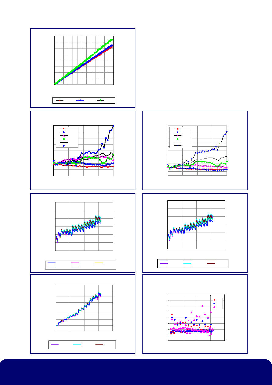
P35-4304-000-200
Thinking RF solutions
www.bookham.com
Attenua tion v s State
0
5
10
15
20
25
30
35
40
0 5 10 15 20 25 30 35 40 45 50 55 60 65
State
Attenuation (dB)
2GHz
8GHz
16GHz
Phase Variation Relative to Previous State
-2
-1
0
1
2
3
4
5
6
0
4
8
12
16
Frequency (GHz)
Phase (Deg)
0.5dB
1dB
2dB
4dB
8dB
16dB
Phase Variation Relative to Reference
State
-2
-1
0
1
2
3
4
5
6
7
8
9
10
0
4
8
1
6
Frequency (GHz)
Phase (Deg)
0 .5 dB
1 dB
2 dB
4 dB
8 dB
1 6dB
Setting Error 8GHz
-1.0
-0.5
0.0
0.5
1.0
1.5
2.0
0
10
20
3
0
Attenuation Setting (dB)
Absolute Attenuation Error (dB)
-40 Deg C
-35 Deg C
-30 Deg C
-25 Deg C
0 Deg C
25 Deg C
50 Deg C
75 Deg C
Setting Error 8GHz
-1.0
-0.5
0.0
0.5
1.0
1.5
2.0
0
10
20
3
0
Attenuation Setting (dB)
Absolute Attenuation Error (dB)
-40 Deg C
-35 Deg C
-30 Deg C
-25 Deg C
0 Deg C
25 Deg C
50 Deg C
75 Deg C
Setting Error 16GHz
-1
0
1
2
3
4
5
6
7
0
10
20
30
40
Attenuation Setting (dB)
Absolute Attenuator Error (dB)
-40 Deg C
-35 Deg C
-30 Deg C
-25 Deg C
0 Deg C
25 Deg C
50 Deg C
75 Deg C
Step Size Between
Adjacent Attenuation Settings
0.0
0.3
0.5
0.8
1.0
1.3
1.5
1.8
2.0
0
20
40
6
0
State
Attenuation Step (dB)
2GHz
8GHz
16GHz

Attenuator Schematic
Chip Outline
P35-4304-000-200
Pad Function Pad Function
1
Rf Input
11
A1
2
B5
12
A3*
3
A5
13
B3*
4
A2*
14
RF Output
5
B2*
15
B3*
6
A4
16
A3*
7
B4
17
A6*
8
B6*
18
B6*
9
A6*
19
B2*
10
B1
20
A2*
Thinking RF solutions
www.bookham.com
Die size:
3.45 x 1.42mm
Bond pad size
120 µm x 120 µm
Die thickness:
200 µm
*Note: option of alternative bond pads on opposite side of die

MMICS
Bookham Technology plc
Caswell
Towcester
Northamptonshire
NN12 8EQ
UK
∑ Tel: +44 (0) 1327 356 789
∑ Fax: +44 (0) 1327 356 698
rfsales@bookham.com
Important Notice
Bookham Technology has a policy of
continuous improvement. As a result
certain parameters detailed on this flyer
may be subject to change without notice.
If you are interested in a particular product
please request the product specification
sheet, available from any RF sales
representative.
www.bookham.com
462/SM/02427/200 Issue 2
© Bookham Technology 2003 Bookham is a registered trademark of Bookham Technology plc
Handling, Mounting and Bonding Instructions
The back of the die is gold metallized and can be die-attached manually onto gold,
eutectically with Au-Sn (80:20) or with low temperature conductive epoxy. The
maximum allowable die temperature is 310 ∞C for 2 minutes. Bonds should be made
onto the exposed gold pads with 17 or 25 microns pure gold or half-hard gold wire.
Bonding should be achieved with the die face at 225 ∞C to 275 ∞C with a heated
thermosonic wedge (approx. 125 ∞C) and a maximum force of 60 grams. Ball bonds
may be used but care must be taken to ensure the ball size is compatible with the
bonding pads shown. The length of the bond wires should be minimised to reduce
parasitic inductance, particularly those to the RF and ground pads.
Ordering Information
P35-4304-000-200
P35-4304-000-200