Specifications are subject to change without notice.
Customers should verify actual device performance in their specific applications.
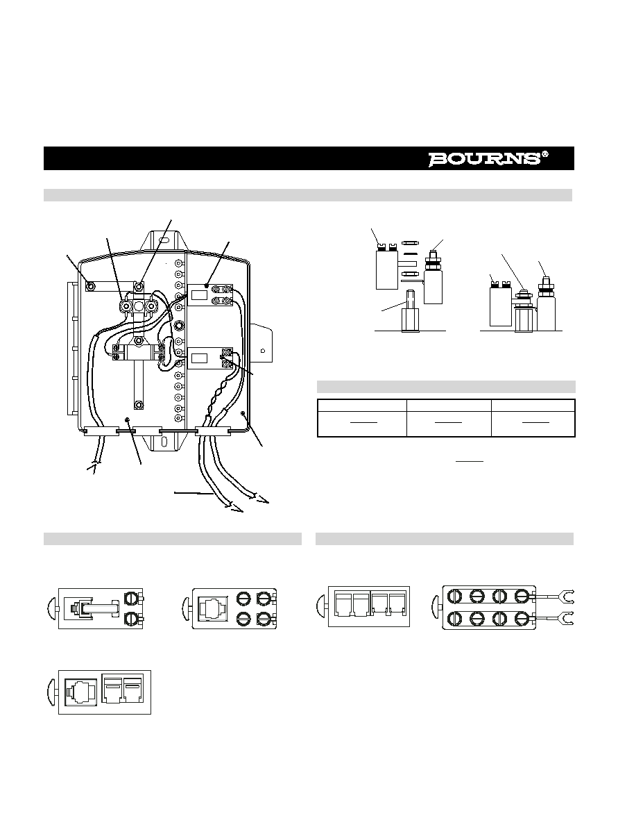
Features
Expands to add POTS lines, DSL or both
Manufactured from high-impact resistant,
ultraviolet-desensitized, flame retardant,
UL Recognized plastic
Optional sealed switching jacks with
Insulation DIsplacement Connectors
(IDCs)
Subscriber lockable with Telco override
7090 Series ≠ Network Interface Device
How To Order
Bourns
Æ
7090 NID provides a secure and weather resistant enclosure for Telco service for residential or commercial installa-
tions. The 7090 supplies station protection and test access points and can be configured for a maximum of six POTS lines or
three lines with DSL. The 7090 features plenty of working space for wire management.
Convenient ground attachment
Listed per UL 497 (File: E53117)
Model Number Designator
Number of Twisted Pairs
1 = One
3 = Three
5 = Five
2 = Two
4 = Four
6 = Six
Station Protector Options
D
1
= 455HS-MSP (2377-45-HS) Voice / DSL / Data (UL, cUL)
Z
1
= 455HS-BC* (2377-45-BC) Balance-Sensitive DSL (UL, cUL)
E
2
= 155HS-MSP (2378-35-HS) Voice / DSL / Data (UL, cUL)
Y
2
= 155HS-BC* (2378-35-BC) Balance-Sensitive DSL (UL, cUL)
B = 125EW (2374-01) Dual Gas Tube (UL, cUL, Telcordia)
C = 125EW-R (2375-01) Dual Gas Tube (UL, cUL, RUS)
L = 356M (2377-01) Balanced Gas Tube (UL, cUL, RUS)
M = J130S (2380-27-01) Solid State Protector (UL, cUL)
T = Tii355M
O = No Station Protectors (Not available with DSL Configurations)
*For DSL systems requiring capacitive balance within 1 pF.
Note 1 = Digi.Guard - 356 size, RUS Maximum Duty
Note 2 = Digi.Guard II - 125 size, RUS Heavy Duty
Special Options
G = Security Screw in Telco Cover
H =
Security Screw in security plate
S =
Sealed Switching Jack w/IDC (85122-T-IDC)
F =
Sealed Switching Jack 4-Post (85122-T4)
B =
Expansion Bridge w/Binding Posts (85122-B)
I =
Expansion Bridge w/IDC (85122-IDC)
O =
No options (standard 85122 jack)
DSL Options
A1 = (1) 3610A ADSL POTS Splitter
P1 = (1) 3610A2 DSL 2+ POTS Splitter
V1 = (1) 3630A VDSL POTS Splitter
A2 = (2) 3610A ADSL POTS Splitters
P2 = (2) 3610A2 DSL 2+ POTS Splitters
V2 = (2) 3630A VDSL POTS Splitters
A3 = (3) 3610A ADSL POTS Splitters
P3 = (3) 3610A2 DSL 2+ POTS Splitters
V3 = (3) 3630A VDSL POTS Splitters
DSL Configuration Note:
The 3610A, 3610A2 and 3630A must be ordered with options D, Z, E or Y Station Protectors. 7090 NIDs ordered with DSL units
will include Special Option F (4-post sealed switching jacks). Example: 7090-01-EF-A1
DSL Equalization Option
R1 = (1) 3660 Equalization Module
To add lines, use station protector +
85122
Standard Jack (Not available with DSL configurations)
85122-T4
Sealed Switching Jack, 4-post
85122-T-IDC Sealed Switching Jack w/IDC
7090 - 0X - X X - XX - XX
UL
Æ