*RoHS Directive 2002/95/EC Jan 27 2003 including Annex.
"Fluorinert" is a registered trademark of 3M Co.
Specifications are subject to change without notice.
Customers should verify actual device performance in their specific applications.
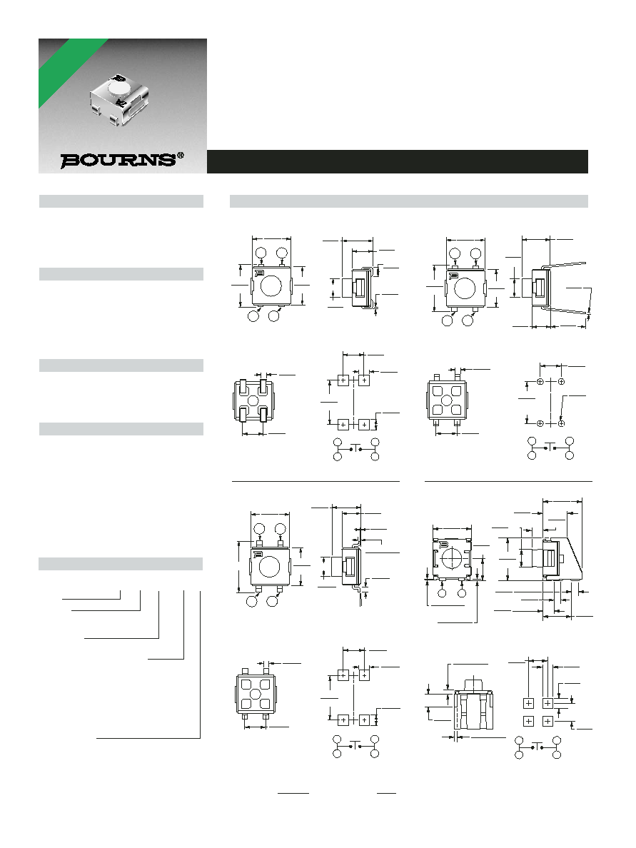
7914 4 mm SMD & Through-hole Sealed Key Switch
Electrical Characteristics
Contact Rating
Maximum Current ...............100 mA max.
Maximum Voltage .............................16 V
Contact Resistance .......100 milliohms max.
Insulation Resistance ...100 megohms min.
Dielectric Strength ........................250 VAC
General Characteristics
Switch Type .........................Normally open
Operating Temperature Range
....................................-55 įC to +125 įC
Storage Temperature Range
....................................-55 įC to +125 įC
Seal Test ...........................85 įC Fluorinert
Vibration ..............................................20 G
Shock ................................................100 G
Mechanical Characteristics
Actuator Force .........................300 Ī 100 g
Pushover Strength (S Style)
...............................2 kilograms minimum
Cycle life, loaded ..........100,000 actuations
Contact resistance .......100 milliohms max.
Physical Characteristics
Cover Material......................Stainless steel
Base Material .......Thermoplastic, UL94V-0
Terminal Material .............Phosphor bronze
Dome Material......................Stainless steel
Actuator Material.............High temperature
silicon rubber
Marking ......................Manufacturer's code
and date code
Packaging Options
J & G .............500 pcs./reel; 50 pcs./tube
S..................200 pcs./reel; 100 pcs./tube
H ..........................................50 pcs./tube
Features
Compatible with most surface mount
Meets EIA/EIAJ/IPC/VRCI SMD standard
soldering processes
outline dimensions
Compatible with popular vacuum pick-and-
Top or side actuated
place equipment
RoHS compliant*
J-hook, gull-wing & pinned configurations
Sealed for board washing
How to Order
7914 J - 1 - 000 E
Model
Terminal
J = J-Hook
H = Through-hole
G = Gull Wing S = Right Angle
Switch Type
1 = N.O. Au Contacts
Product Code for Button Height
(For Styles J, G and H)
000 = 4.0 mm FMS
024 = 2.4 mm FMS (Flush Actuator)
032 = 3.2 mm FMS
050 = 5.0 mm FMS
(For Style S)
000 = 1.68 mm FTS
032 = 0.91 mm FTS
024 = Flush Actuator
050 = 2.7 mm FTS
Embossed Tape
(Option Applicable to Styles J, G and S only -
Consult Factory. Omit for Tube packaging.)
G, J = 500 pcs./reel
S = 200 pcs./reel
FMS = From Mounting Surface
FTS = From Top Surface
Product Dimensions
EXCEPT WHERE NOTED.
1
2
2
1
SPST N.O.
5.00
(.197)
2 PLCS.
0.20
(.008)
2
1
2
1
2.54
(.100)
0.76
(.030)
TYP.
TYP.
TYP.
TYP.
TYP.
TYP.
2 PLCS.
2 PLCS.
DIA. TYP.
2 PLCS.
TYP.
TYP.
TYP.
TYP.
2 PLCS.
2
1
2
1
4.80
(.189)
4.50
(.177)
2.40
(.094)
0.60
(.024)
0.05 Ī 0.05
(.002 Ī .002)
0.20
TYP.
(.008)
5į MAX TYP
2.54
TYP.
(.100)
3.8
(.150)
1.27
(.050)
1.78
(.070)
2.54
(.100)
0.76
(.030)
2
1
2
1
4.80
(.189)
4.50
(.177)
5.00
(.197)
2.54
(.100)
1.00
(.039)
0.20
(.008)
7914J
J-Hook
7914H
Through-hole
7914S
Right Angle
7914G
Gull Wing
1
2
2
1
SPST N.O.
1
2
2
1
SPST N.O.
6.20
4.00
(.157)
2.40
(.094)
2.54
TYP.
(.100)
5.5
(.217)
1.27
(.050)
4.00
(.157)
2.40
(.094)
0.80
(.031)
RECOMMENDED PCB LAYOUT
RECOMMENDED PCB LAYOUT
RECOMMENDED PCB LAYOUT
5.00
(.197)
RECOMMENDED PCB LAYOUT
1
2
2.86
(.113)
0.13 Ī 0.05
(.005 Ī .002)
0.2 Ī 0.13
(.008 Ī .005)
0.38 Ī 0.2
(.015 Ī .008)
2.54
(.100)
1.3
TYP.
(.051)
2.33
(.092)
1.25
TYP.
(.049)
1
2
2
1
SPST N.O.
1.78
(.070)
2.54
(.100)
2.54
(.100)
0.76
(.030)
5.00
(.197)
4.80
(.189)
4.50
(.177)
2.40
(.094)
2.40
(.094)
4.00
(.157)
4.00
(.157)
5.18
(.204)
1.68
(.066)
2.75
(.108)
0.48 Ī 0.2
(.019 Ī .008)
1.68
(.066)
5.44
(.214)
2.38
(.094)
DIA.
0.89
(.035)
0.78
(.031)
1.5
(.059)
3.89
(.153)
7A
7A
7A
7A
DIMENSIONS :
MM
(INCHES)
TOLERANCES :
0.2
(.008)
*RoHS COMPLIANT

Specifications are subject to change without notice.
Customers should verify actual device performance in their specific applications.
TAPE
REEL
Meets EIA specification 481.
.30
MAX.
(.012)
4.3 Ī .10
(.169 Ī .004)
5.50 Ī 0.05
(.217 Ī .002)
1.5 + .10/ ≠.00
(.059 + .004/ ≠.00)
DIA.
4.00 Ī .10
(.157 Ī .004)
5.26 Ī .10
(.207 Ī .004)
5.26 Ī .10
(.207 Ī .004)
8.00 Ī .20
(.315 Ī .008)
12.00 Ī .30
(.472 Ī .012)
1.75 Ī .10
(.069 Ī .004)
2.00 Ī .05
(.079 Ī .002)
13.0 Ī .50
(.512 Ī .020)
DIA.
20.0
(.787)
DIA.
1.5 Ī .254
(.059 Ī .010)
EQUAL SPACED 3 PLCS.
178 Ī 2
(7.008 Ī .079)
DIA.
12.4
(.488)
50.0
(1.969)
MIN.
TAPE
178 Ī 2
(7.008 Ī .079)
DIA.
13.0 Ī .50
(.512 Ī .020)
DIA.
1.5 Ī .254
(.059 Ī .010)
EQUAL SPACED 3 PLCS.
20.0
(.787)
DIA.
50.0
(1.969)
MIN.
12.4
(.488)
REEL
4.3 Ī .10
(.169 Ī .004)
.30
MAX.
(.012)
5.50 Ī 0.05
(.217 Ī .002)
1.5 + .10/ ≠.00
(.059 + .004/ ≠.00)
DIA.
4.00 Ī .10
(.157 Ī .004)
2.00 Ī .05
(.079 Ī .002)
8.00 Ī .20
(.315 Ī .008)
1.75 Ī .10
(.069 Ī .004)
12.00 Ī .30
(.472 Ī .012)
5.26 Ī .10
(.207 Ī .004)
6.48 Ī .10
(.255 Ī .004)
Meets EIA specification 481.
7914J/G
2.82
(.111)
.508
(.020)
TYP
2 PLCS
2.82
(.111)
4.69
(.185)
7.67
(.302)
R
.508
(.020)
TYP
R
.762
(.030)
MAX 2 PLCS
60ļĪ 2ļ
7914H
5.66 Ī .254
(.223 Ī .010)
8.89 Ī .254
(.350 Ī .010)
8.64 Ī .254
(.340 Ī .010)
2.82
(.111)
.508
(.020)
TYP
1.78
(.070)
2.54
(.100)
4.24
(.167)
R TYP
.508
(.020)
R MAX TYP
.762
(.030)
13ļ Ī 2ļ 2 PLCS REF
7914S
1.02
(.040)
3.56
(.140)
5.84
(.230)
.508
(.020)
TYP
2.03
(.080)
2.92
(.115)
1.47
(.058)
5.97
(.235)
7914J
7914G
7914S
6.0
(.236)
0.3 Ī 0.05
(.012 Ī .002)
10.0
(.394)
2.0
(.079)
7.5
(.295)
12.0
(.472)
4.0
(.157)
1.75
(.069)
16.0 Ī 0.3
(.630 Ī .012)
5.3
(.209)
5.4
(.213)
7.4 + 0.25/ -0.10
(.291 + .010/ - .004)
0
1.5
(.059)
MIN
0
1.5 + 0.1/0
(.059 + .004/0)
50.0
(1.969)
16.0
(.630)
MIN.
177.8 Ī 2.032
(7.00 Ī .080)
DIA.
40.0
(1.575)
MIN. DIA.
ACCESS HOLE
AT SLOT LOCATION
16.0
(.630)
DIA.
20.19
(.795)
MIN. DIA.
1.49
(.059)
MIN. EQUAL SPACED 3 PLCS
Packaging Specifications
7914 4 mm SMD & Through-hole Sealed Key Switch
500 pcs./reel
500 pcs./reel
200 pcs./reel
50 pcs./tube
50 pcs./tube
100 pcs./tube
Reflow Soldering Profile
T
e
mperature (
į
C)
Time (Seconds)
275
30-40 Sec.
120 įC
225
175
125
75
25
0
20
40
60
80
100 120 140 160 180 200
80-90 Sec.
10-15
Sec.
35-60
Sec.
180 įC
240 įC
REV. 04/06