 | –≠–ª–µ–∫—Ç—Ä–æ–Ω–Ω—ã–π –∫–æ–º–ø–æ–Ω–µ–Ω—Ç: 8182 | –°–∫–∞—á–∞—Ç—å:  PDF PDF  ZIP ZIP |

Specifications are subject to change without notice.
Customers should verify actual device performance in their specific applications.
81/82 - 5/8 " Square Single-Turn Panel Control
85/86 - 5/8 " Square Single-Turn Panel Control with Rotary Switch
Initial Electrical Characteristics
1
Conductive Plastic Element
Cermet Element
Standard Resistance Range
Linear Tapers (A, B, E, & H) ................................................................(B & E) 1 K ohms to 1 megohm ...................(A & H) 100 ohms to 1 megohm
Audio Tapers (C, D, F, G, S, & T)........................................................(D, G, S, & T) 1 K ohms to 1 megohm .........(C & F) 1 K ohms to 1 megohm
Total Resistance Tolerance .....................................................................±20 % or 10 % ............................................±10 % or 5 %
Independent Linearity .............................................................................±5 % ............................................................±5 %
Absolute Minimum Resistance ...............................................................2 ohms maximum ........................................2 ohms maximum
Effective Electrical Angle ........................................................................(Linear tapers) 240 ∞ ± 5 ∞............................(Linear tapers) 240 ∞ ± 6 ∞
(Audio tapers) 225 ∞ ± 5 ∞
(Audio tapers) 225 ∞ ± 6 ∞
Contact Resistance Variation .................................................................±1 % ............................................................±1 % or 3 ohms (whichever is greater)
Dielectric Withstanding Voltage (MIL-STD-202, Method 301)
Sea Level............................................................................................1,500 VAC minimum ....................................1,500 VAC minimum
70,000 Feet ........................................................................................500 VAC minimum .......................................500 VAC minimum
Insulation Resistance (500 VDC) ............................................................1,000 megohms minimum...........................1,000 megohms minimum
Power Rating At 70 ∞C (Voltage Limited By Power Dissipation or 350 VAC, Whichever Is Less)
+70 ∞C Single Section Assembly .......................................................(Linear tapers) 0.5 watt................................(Linear tapers) 2 watts
(Audio tapers) 0.25 watt
(Audio tapers) 1 watt
+70 ∞C Multiple Section Assembly.....................................................(Linear tapers) 0.5 watt/section ...................(Linear tapers) 1 watt/section
(Audio tapers) 0.25 watt/section
(Audio tapers) 0.5 watt/section
+125 ∞C ..............................................................................................0 watt...........................................................0 watt
Theoretical Resolution ............................................................................Essentially infinite ........................................Essentially infinite
Environmental Characteristics
1
Operating Temperature Range ...............................................................-40 ∞C to +125 ∞C........................................-40 ∞C to +125 ∞C
Storage Temperature Range...................................................................-55 ∞C to +125 ∞C........................................-55 ∞C to +125 ∞C
Temperature Coefficient Over Storage Temperature Range...................±1,000 ppm/∞C ............................................±150 ppm/∞C
Vibration (Single Section)........................................................................15 G .............................................................15 G
Total Resistance Shift.........................................................................±2 % maximum ...........................................±2 % maximum
Voltage Ratio Shift..............................................................................±5 % maximum ...........................................±5 % maximum
Shock (Single Section)............................................................................30 G .............................................................30 G
Total Resistance Shift.........................................................................±2 % maximum ...........................................±2 % maximum
Voltage Ratio Shift..............................................................................±5 % maximum ...........................................±5 % maximum
Load Life .................................................................................................1,000 hours..................................................1,000 hours
Total Resistance Shift.........................................................................±10 % maximum .........................................±5 % maximum
Rotational Life (No Load) ........................................................................100,000 cycles ............................................100,000 cycles
Total Resistance Shift.........................................................................(Linear taper) 10 ohms or ±10 % TRS max. .(All tapers) ±5 % TRS maximum
(whichever is greater)
(Audio taper) ±20 % maximum
Contact Resistance Variation @ 50,000 cycles
(Audio taper) ................................................................................±3 % ............................................................±3 %
(Linear taper) ...............................................................................±2 % ............................................................±2 %
Moisture Resistance (MIL-STD-202, Method 103, Condition B)
Total Resistance Shift.........................................................................(B & E tapers) ±10 % maximum .................±5 % maximum (all tapers)
(D, G, S & T tapers) ±20 % maximum
Insulation Resistance (500 VDC) ........................................................100 megohms minimum..............................100 megohms minimum
IP Rating .................................................................................................IP 40 ............................................................IP 40
Mechanical Characteristics
1
Stop Strength
1/4 " and 1/8 " diameter shafts..............................................................................................................................................................45.19 N-cm (4 lb.-in.)
7/8 " length shaft ....................................................................................................................................................................................22.6 N-cm (2 lb.-in.)
Mechanical Angle ........................................................................................................................................................................................................300 ∞ ±5 ∞
Torque
Starting and Running Torque (Non-Locking Bushings)
Single Section ..........................................................................................................................................................0.14 to 1.06 N-cm (0.2 to 1.5 oz.-in.)
Dual Section ..............................................................................................................................................................0.14 to 1.06 N-cm (0.2 to 1.5 oz.-in.)
Triple Section ............................................................................................................................................................0.35 to 1.41 N-cm (0.5 to 2.0 oz.-in.)
Quadruple Section ....................................................................................................................................................0.35 to 1.41 N-cm (0.5 to 2.0 oz.-in.)
Starting and Running Torque (Locking Bushings) ........................................................................................................0.14 to 2.82 N-cm (0.2 to 4.0 oz.-in.)
Shaft Locking Torque with Locknut @ 10 in-lb. (B & E Bushings) ............................................................................................................14 N-cm (20 oz-in.)
Mounting ......................................................................................................................................................................1.7-2.0 N-m (15-18 lb.-in.) maximum
Weight (Single Section) ................................................................................................................................................................................21 grams maximum
(Each Additional Section) ..........................................................................................................................................................................6 grams maximum
Terminals ............................................................................................................................................................................Printed circuit terminals or J-Hooks
Soldering Condition ......................................................................Recommended hand soldering using Sn95/Ag5 no clean solder, 0.025 " wire diameter.
Maximum temperature 399 ∞C (750 ∞F) for 3 seconds. No wash process to be used with no clean flux.
Marking ............................................................................Manufacturer's trademark, wiring diagram, date code and resistance, manufacturer's part number
Ganging (multiple section potentiometers) ........................................................................................................................................................4 cup maximum
Hardware ............................................One lockwasher and one mounting nut is shipped with each potentiometer, except where noted in the part number.
NOTE: Model 81/82 performance specifications do not apply to units subjected to printed circuit board cleaning procedures.
1
At room ambient: +25 ∞C nominal and 50 % relative humidity nominal, except as noted.
Features
Metal shaft and bushing
Consistent, smooth quality feel
Up to 4 sections available
Rotary switch option designed
for "on-off" function control
RoHS compliant versions available*
For dimensional drawings see pages 3 & 4.
For ordering information see page 5.
Potentiometer Specifications
*RoHS COMPLIANT
VERSIONS
AVAILABLE
*RoHS Directive 2002/95/EC Jan 27 2003 including Annex

Specifications are subject to change without notice.
Customers should verify actual device performance in their specific applications.
81/82 - 5/8 " Square Single-Turn Panel Control
85/86 - 5/8 " Square Single-Turn Panel Control with Rotary Switch
Rotary Switch Specifications
Initial Electrical Characteristics
1
Contacts:
DPST ..................................................................................................................................................................................N.O/N.O.,N.C./N.C. or N.O./N.C.
DPDT....................................................................................................................................................................................2 N.O./N.C. (break before make)
Power Rating (Resistive Load):
DPST ................................................................................................................2 A @ 125 volts RMS-60 Hz or 2 A @ 28 VDC, 1 A @ 250 volts RMS-60 Hz
DPDT ..............................................................................................................................................................1 A @ 125 volts RMS-60 Hz or 1 A @ 28 VDC
Contact Resistance (0.1 VDC-10 mA)........................................................................................................................................................10 milliohms nominal
Contact Bounce ..................................................................................................................................................................................5 milliseconds maximum
Dielectric Withstanding Voltage (MIL-STD-202, Method 301)
Sea Level ................................................................................................................................................................................................1500 VAC minimum
Insulation Resistance ..........................................................................................................................................................................1000 megohms minimum
Environmental Characteristics
1
Operating Temperature Range ............................................................................................................................................................................0 ∞C to +70 ∞C
Storage Temperature Range ..........................................................................................................................................................................-65 ∞C to +125 ∞C
Vibration (Dual Section) ..........................................................................................................................................................................................................8 G
Contact Resistance ............................................................................................................................................................................10 milliohms maximum
Contact Bounce..............................................................................................................................................................................0.1 millisecond maximum
Shock (Dual Section) ............................................................................................................................................................................................................20 G
Contact Resistance ............................................................................................................................................................................10 milliohms maximum
Contact Bounce..............................................................................................................................................................................0.1 millisecond maximum
Rotational Life ........................................................................................................................................................................................................25,000 cycles
Switch Actuating Torque (50% Duty cycle @ Rated Power Load) ......................................................................................1.41 to 4.94 N-cm (2 to 7 oz.-in.)
Contact Resistance ..........................................................................................................................................................................100 milliohms maximum
Moisture Resistance (MIL-STD-202, Method 106, Condition B)
Contact Resistance (0.1 VDC-10 mA) ................................................................................................................................................10 milliohms maximum
Insulation Resistance (After 24 Hours @ Room Temperature) (500 VDC) ........................................................................................100 megohms minimum
Switch Housing Material ....................................................................................................................High temperature, flame retardant, thermosetting plastic
Mechanical Characteristics
1
Actuating Torque (Each Section, Switch Module Only) ........................................................................................................3.53 to 10.6 N-cm (5 to 15 oz.-in.)
Running Torque (Out of Detent, 2-4 Module Assembly) ......................................................................................................0.21 to 1.41 N-cm (0.3 to 2 oz.-in.)
Detent........................................................................................................................................................................................................CW or CCW standard
Actuation Angle ....................................................................................................................................................................................................................25 ∞
Contact Materials ............................................................................................................................................................................Fine silver with gold overlay
Terminal Styles ....................................................................................................................................................................................................Solder lug only
Standard Orientation ..................................................................................................................................................................In-line with control terminals
Optional ..............................................................................................................................................................................Rotated 90 ∞ CCW from standard
Terminal Strength (Before and After Soldering Heat Exposure) ............................................................................................................0.9 Kg (2 lbs.) minimum
NOTE: Model 81/82 performance specifications do not apply to units subjected to printed circuit board cleaning procedures.
1
At room ambient: +25 ∞C nominal and 50 % relative humidity nominal, except as noted.

Specifications are subject to change without notice.
Customers should verify actual device performance in their specific applications.
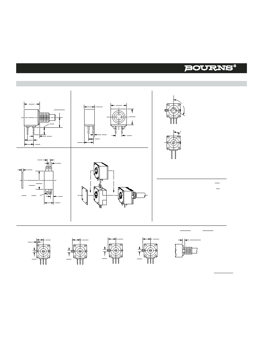
81/82 - 5/8 " Square Single-Turn Panel Control
"A" Bushing
3/8 " (9.53 mm) Dia. Plain - Single Shaft
3/8-32 UNEF
"B" Bushing
3/8 " (9.53 mm) Dia. Plain - Single Shaft
3/8-32 UNEF
4.45
(.175)
MIN.
"C" Bushing
1/4 " (6.35 mm) Dia. Plain - Single Shaft
"C" Bushing
1/4 " (6.35 mm) Dia. Plain - Concentric Shaft
3/8-32 UNEF
TRIPLE CONCENTRIC
(SPECIAL ORDER)
1/4-32 UNEF
"A" Bushing
3/8 " (9.53 mm) Dia. Plain - Concentric Shaft
1/4-32 UNEF
"E" Bushing
1/4 " (6.35 mm) Dia. Locking - Single Shaft
Dual Unit - PC Pins & J-Hook
Triple Unit - PC Pins & J-Hook
Quad Unit - PC Pins & J-Hook
FLATTED SHAFT
120 ∞ ± 5 ∞ CCW END
Shaft Flat Orientation*
SLOTTED SHAFT
1 2 3
30 ∞ ±5 ∞
*EXCLUDES MODELS 83 AND 84
Model 81
Suggested PC Board Layout - PC Pins
(Single-Shaft Style Bottom View)
Note: For units with dual concentric shaft styles, a
.100 (2.54) spacer is added between the module(s) driven
by the outer shaft and those driven by the inner shaft.
For G, K, or V shafts, add the spacer between
modules 1 and 2. For L or M shafts, add the spacer
between modules 2 and 3. For N or P shafts, add the
spacer between modules 3 and 4.
Model 81/82
Single Unit - PC Pins & J-Hook
Terminal outlines shown as solid lines represent PC Pins, available
on Model 81. Dashed line terminal outline represents "J" Hook,
available on Model 82.
1
3
2
9.50 ± .38
(.375 ±.015)
12.7,15.88,19.05,22.23± .79
(1/2, 5/8, 7/8, ± 1/32)
STANDARD
DIA.
(.063+.015/-.000)
SHAFT SLOT
1.19
WIDE X
1.60+.38/-.00
DEEP
(.047)
45 ∞ ±5 ∞ X
45 ∞ ±5 ∞ X
(.010)
CHAMFER
.25
45 ∞ ±5 ∞ X (.010)
CHAMFER
.25
7.92
(.312)
MIN.
9.53 ± .13
(.375 ± .005)
PILOT DIA.
5.49
OPTIONAL FLAT
16.00
LONG OR
1.52
FROM
"A" BUSHING END FOR SHAFTS UNDER
17.46
(.216)
(.63)
(.06)
(11/16)
(.010)
CHAMFER
.25
45 ∞ ±5 ∞ X
(.010)
CHAMFER
.25
(.063 +.015/-.000)
SHAFT SLOT
1.19
WIDE X
1.60 + .38/- .00
DEEP
(.047)
12.70 ± .13
(.500 ± .005)
15.88 ± .79
(5/8 ± 1/32)
STANDARD
6.32 ± .03
(.249 ± .001)
DIA.
9.53 ± .13
(.375 ± .005)
PILOT DIA.
11.13
(.438)
MIN.
6.35 ± .13
(.250 ± .005)
9.53,12.7,15.88,19.05,22.23 ± .79
(3/8, 1/2, 5/8, 3/4, 7/8, ± 1/32)
STANDARD
SHAFT SLOT
.79
WIDE X
.79 ± .25 DEEP
(.031)
(.031 ± .010)
2.39 ± .13 OPTIONAL FLAT 6.35 LONG OR 1.52 FROM
"C" BUSHING END FOR SHAFTS UNDER
14.30
(.094 ± . 005)
(.250)
(.06)
(9/16)
6.35 ± .05
(.250 ± .002)
PILOT DIA.
SHAFT SLOT
.78
WIDE X
.78 ± .03
DEEP
(.031)
(.031 ± .001)
12.7 ± .13
(.500 ± .005)
10.80
(.425)
MIN.
15.88 ± .79
(5/8 ± 1/32)
STANDARD
3.18 ± .03
(.125 ± .001)
DIA.
6.35 ± .05
(.250 ± .002)
PILOT DIA.
28.58 ± .79
(1-1/8 ± 1/32)
STANDARD
19.05 ± .79
(3/4 ± 1/32)
STANDARD
.375
(9.53)
6.32 ± .03
(.249 ±.001)
DIA.
3.162 ± .025
(.1245 ± .001)
DIA.
1.98 ± .03
(.078 ± .001)
DIA.
OUTER SHAFT
7.47
DIA.
OPERATES SECTION #1 INNER SHAFT
3.18
DIA.
OPERATES SECTION #2, #3, & #4 ("G" STYLE)
(.249)
(.125)
OUTER SHAFT
3.18
DIA.
OPERATES SECTION #1 INNER SHAFT
.078
DIA.
OPERATES SECTION #2, #3, & #4 ("G" STYLE)
(.125)
(1.95)
15.88 ± .79
(5/8 ± 1/32)
STANDARD
25.40 ± .79
(1 ± 1/32)
STANDARD
6.35
(.25)
3.162 ± .025
(.1245 ± .001)
DIA.
1.98 ± .03
(.078 ± .001)
DIA.
26.04 ± .79
(1.025 ± .031)
10.16 ± .38
(.400 ± .015)
10.16 ± .38
(.400 ± .015)
TYP.
10.16 ± .38
(.400 ± .015)
TYP.
36.20 ± 1.19
(1.425 ± .047)
46.36 ± 1.19
(1.825 ± .047)
15.88 ± .41
(.625 ± .016)
5.97 ± .38
(.235 ± .015)
5.08 ± .38
(.200 ± .015)
15.88 ± .38
(.625 ± .015)
11.94
(.470)
9.58 ± .38
(.377 ± .015)
15.88 ± .38
(.625 ± .015)
5.33 ± .76
(.210 ± .03)
3.81
(.150)
MAX. 3 PLCS.
.81
(.032)
DIA.
5.08 ± .38
(.200 ± .015)
12.7
(.50)
1.14
(.045)
DIA.
5.08 ± .13
(.200 ± .005)
10.16 ± .13
(.400 ± .005)
5.08 ± .13
(.200 ± .005)
3.162 ± .025
(.1245 ± .001)
DIA.
6.35 ± .03
(1/4 ± 1/32)
1/4-32 UNEF
Product Dimensions
DIMENSIONS ARE:
MM
(INCHES)
Specifications are subject to change without notice.
Customers should verify actual device performance in their specific applications.
REAR
PLATE
COVER
.725
(18.42)
Switch Module
Model 85/86
Primary Potentiometer Module
Model 85/86
Secondary Potentiometer Module
Model 85/86
Locating Lug Options - All Model 80 Series
NOTE: "D" OPTION - NO A/R LUG. OTHER LOCATING LUG OPTIONS AVAILABLE. FOR DETAILS CONSULT FACTORY.
REAR
COVER
PLATE
SWITCH
MODULE
PRIMARY
POTENTIOMETER
MODULE
Assembly Sequence
Model 85/86
Secondary Potentiometer Module
TOLERANCES EXCEPT AS SHOWN: DECIMAL .XXX ± (.005)
.XX ±
(.015)
ANGLE ± 5 %
14.53
(.572)
9.58 ± .38
(.377 ± .015)
12.7
(.50)
5.08
(.200)
5.97
(.235)
8.56
(.337)
10.16
(.400)
1.60
(.063)
8.56
(.337)
5.08
(.200)
15.88
(.625)
15.88
(.625)
5.08
(.200)
1.35
(.053)
2.77
(.109)
TYP. 6 PLACES
2.29
(.090)
(.095)
L X
(.045)
W
SLOT TYP. 6 PLACES
2.41
1.14
2.92
(.115)
9.53
(.375)
.127
.38
A
7.75
(.305)
.46
(.018)
2.31
(.091)
E
3.18
(.125)
13.49
(.531)
J
2.36
(.093)
9.53
(.375)
H
3.18
(.125)
11.10
(.437)
.79 ± .41
(.031 ± .016)
E =
2.36 ± .76
(.093 ± .03)
H & J = 1.98 ± .41
(.078 ± .016)
FLATTED SHAFT
120 ∞ ± 5 ∞ CCW END
Shaft Flat Orientation*
SLOTTED SHAFT
30 ∞ ± 5 ∞
*EXCLUDES MODELS 83 AND 84
85/86 - 5/8 " Square Single-Turn Panel Control with Rotary Switch
DIMENSIONS ARE:
MM
(INCHES)
Product Dimensions
Specifications are subject to change without notice.
Customers should verify actual device performance in their specific applications.
ANTI-ROTATION LUG
A
Single .305 R, 90 ∞CW
B
Double .305 R, 90 ∞ & 270 ∞CW
C
Single .305 R, 270 ∞CW
D
No Lug
E
Single .531 R, 90 ∞CW
F
Single .305 R, 180 ∞CW
J
Single .375 R, 90 ∞CW
K
Double .375 R, 90 ∞ & 270 ∞CW
# SECTIONS
APPLICABLE MODELS
1
Single
81,82
2
Double
81,82,85,86
3
Triple
81,82,85,86
4
Quad
81,82,85,86
AVAILABLE ONLY IN
SHAFT TYPE
LENGTHS
BUSHINGS
(CODE)
(CODE)
A Single Plain 1/4 " (6.35 mm) D
16,20,24,28
A, B, J
B Single Slotted 1/4 " (6.35 mm) D
16,20,24,28
A, B, J
C Single Flatted 1/4 " (6.35 mm) D
20,24,28
A, B, J
E Single Slotted 1/8 " (3.18 mm) D
12,16,20,24,28
C, E, N
F Single Flatted 1/8 " (3.18 mm) D
Consult Factory
C, N
G Dual Concentric Plain 1/4 " (6.35 mm) D - 1/8 " (3.18 mm) D
36,40
A, J
Outer Operates Section 1
K Dual Concentric Plain 1/8 " (3.18 mm) D - 5/64 " (1.98 mm) D
32,36
C, N
Outer Operates Section 1
L Dual Concentric Plain 1/4 " (6.35 mm) D - 1/8 " (3.18 mm) D
36,40
A, J
Outer Operates Section 1/2
M Dual Concentric Plain 1/8 " (3.18 mm) D - 5/64 " (1.98 mm) D
32,36
C, N
Outer Operates Section 1
N Dual Concentric Plain 1/4 " (6.35 mm) D - 1/8 " (3.18 mm) D
36,40
A, J
Outer Operates Section 1/2/3
P Dual Concentric Plain 1/8 " (3.18 mm) D - 5/64 " (1.98 mm) D
32,36
C, N
Outer Operates Section 1/2
R Single Slotted 6 mm D
16,19,22,50
R
T Single Slotted 4 mm D
10, 13, 22
U
V Dual Concentric Plain 6 mm D - 3 mm D
30, 42
R
Outer Operates Section 1
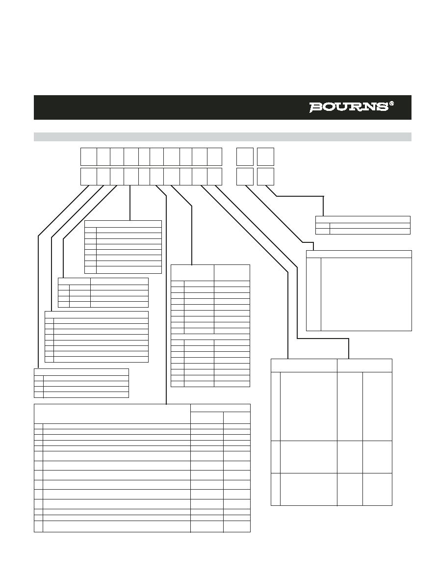
ELEMENT TYPE
RESISTANCE CODE
TAPER/TOLERANCE
VALUE IN OHMS
(A) Linear Cermet ±10 %
(05) - 100
(30) - 15 K
(H) Linear Cermet ±5 %
(28) - 150
(16) - 20 K
(06) - 200
(17) - 25 K
(07) - 250
(18) - 50 K
(08) - 500
(19) - 75 K
(09) - 750
(20) - 100 K
(10) - 1 K
(31) - 150 K
(29) - 1.5 K
(21) - 200 K
(11) - 2 K
(22) - 250 K
(12) - 2.5 K
(23) - 500 K
(13) - 5 K
(24) - 750 K
(14) - 7.5 K
(25) - 1 M
(15) - 10 K
(B) Linear C-P ±20 %
(10) - 1 K
(18) - 50 K
(E) Linear C-P ±10 %
(12) - 2.5 K
(20) - 100 K
(13) - 5 K
(22) - 250 K
(15) - 10 K
(23) - 500 K
(16) - 20 K
(25) - 1 M
(17) - 25 K
(C) CW Audio Cermet ±10 %
(10) - 1 K
(18) - 50 K
(D) CW Audio C-P ±20 %
(12) - 2.5 K
(20) - 100 K
(F) CCW Audio Cermet ±10 %
(13) - 5 K
(22) - 250 K
(G) CCW Audio C-P ±20 %
(15) - 10 K
(23) - 500 K
(S) CW Audio C-P ±10 %
(17) - 25 K
(25) - 1 M
(T) CCW Audio C-P ± 10 %
(18) - 50 K
SHAFT
AVAILABLE
LENGTH
ONLY IN
(FMS)
BUSHING
Code Description
Code
12
3/8 "L
C, N, J
16
1/2 "L
A, C, J, N
20
5/8 "L
A, B, C, E, J, N
24
3/4 "L
A, B, C, E, J, N
28
7/8 "L
A, B, C, E, J, N
32
1 "L
A, B, C, E, J, N
36
1-1/8 "L
A, B, C, E, J, N
40
1-1/4 "L
A, B, C, E, J, N
METRIC
10
10 mmL
U
13
13 mmL
U
16
16 mmL
R
19
19 mmL
R
22
22 mmL
R, U
30
30 mmL
R
42
42 mmL
R
50
50 mmL
R
Boldface features are Bourns standard options.
All others are available with higher minimum order
quantities.
Models 81 & 82: Part number for multiple section potentiometers
must have a taper and resistance value for each section.
Models 85 & 86: Part number must contain a switch type.
SWITCH TYPE (MODELS 85 & 86 ONLY)
(R50) DPST N.O./N.C. CW Detent In-Line Term
(R51) DPST N.O./N.C. CCW Detent In-Line Term
(R52) DPST N.O./N.O. CW Detent In-Line Term
(R53) DPST N.O./N.O. CCW Detent In-Line Term
(R54) DPST N.C./N.C. CW Detent In-Line Term
(R55) DPST N.C./N.C. CCW Detent In-Line Term
(R56) DPST N.O./N.C. CW Detent Horz Term
(R57) DPST N.O./N.C. CCW Detent Horz Term
(R58) DPST N.O./N.O. CW Detent Horz Term
(R59) DPST N.O./N.O. CCW Detent Horz Term
(R60) DPST N.C./N.C. CW Detent Horz Term
(R61) DPST N.C./N.C. CCW Detent Horz Term
(R70) DPDT CW Detent In-Line Term
(R71) DPDT CCW Detent In-Line Term
(R72) DPDT CW Detent Horz Term
(R73) DPDT CCW Detent Horz Term
BUSHING
A Plain 3/8 " (9.53 mm) D x 3/8 " (9.65 mm) L
B Locking 3/8 " (9.65 mm) D x 1/2 " (12.7 mm) L
C Plain 1/4 " (6.35 mm) D x 1/4 " (6.35 mm) L
E Locking 1/4 " (6.35 mm) D x 1/2 " (12.7 mm) L
J Plain 3/8 " (9.65 mm) D x 1/4 " (6.35 mm) L
N Plain 1/4 " (6.35 mm) D x 3/8 " (9.65 mm) L
R Plain 10 mm D x 9 mm L
U Plain 7 mm D x 6 mm L
MODEL
81 Single-Turn, PC Pins
82 Single-Turn, J-Hooks
85 Single-Turn, Pot/Rotary Switch, PC Pins
86 Single-Turn, Pot/Rotary Switch, J-Hooks
A 15
81/82 - 5/8 " Square Single-Turn Panel Control
85/86 - 5/8 " Square Single-Turn Panel Control with Rotary Switch
How to Order
REV. 04/06
81 A 2 A - B 28 - A 15 /
R51
L
L
85 A 2 A - B 28 - A 15 /
POTENTIOMETER TYPE
L
RoHS Compliant
Blank Standard