
Features
Radial Leaded Devices
Cured, flame retardant epoxy polymer
insulating material meets UL 94V-0
requirements
Lead free option available
Agency recognition:
Applications
Almost anywhere there is a load to be
protected with a voltage supply of up to
90 V, including:
Broadband cable power passing taps
Set-top boxes
One Hour
Maximum
Nominal
Ihold
Itrip
Initial
Post-Trip
Time
Tripped
Resistance
Resistance
To Trip
Power
Values
Standard Trip
Dissipation
V max.
I max.
Amps
Amps
Ohms
Ohms
Amps
Seconds
Watts
Model
Volts
Amps
at 23 �C
at 23 �C
at 23 �C
at 23 �C
at 23 �C
at 23 �C
at 23 �C
Hold
Trip
Min.
Max.
Max.
Typ.
MF-R055/90
90
10
0.55
1.1
0.45
0.9
2.0
1.6
60
2.0
MF-R055/90U
90
10
0.55
1.1
0.45
0.9
2.0
1.6
28
2.0
MF-R075/90
90
10
0.75
1.5
0.37
0.75
1.65
2.0
60
2.5
T V Rheinland
Specifications are subject to change without notice.
Customers should verify actual device performance in their specific applications.
MF-R/90 Series -
PTC Resettable Fuses
Electrical Characteristics
Thermal Derating Chart - Ihold / Itrip (Amps)
Ambient Operating Temperature
Model
-40 �C
-20 �C
0 �C
23 �C
40 �C
50 �C
60 �C
70 �C
85 �C
MF-R055/90
0.85 / 1.7
0.75 / 1.5
0.65 / 1.3
0.55 / 1.1
0.45 / 0.9
0.4 / 0.8
0.35 / 0.7
0.3 / 0.6
0.22 / 0.44
MF-R055/90U
0.85 / 1.7
0.75 / 1.5
0.65 / 1.3
0.55 / 1.1
0.45 / 0.9
0.4 / 0.8
0.35 / 0.7
0.3 / 0.6
0.22 / 0.44
MF-R075/90
1.15 / 2.3
1.0 / 2.0
0.9 / 1.8
0.75 / 1.5
0.61 / 1.22
0.55 / 1.1
0.48 / 0.96
0.41 / 0.82
0.30 / 0.6
"U" suffix indicates product without insulation coating.
Operating/Storage Temperature ........................-40 �C to +85 �C
Maximum Device Surface Temperature
in Tripped State ................................................125 �C
Passive Aging......................................................+85 �C, 1000 hours ....................................�5 % typical resistance change
Humidity Aging....................................................+85�C, 85% R.H. 1000 hours......................�5 % typical resistance change
Thermal Shock ....................................................+125 �C to -55 �C, 10 times ........................�10 % typical resistance change
Solvent Resistance ............................................MIL-STD-202, Method 215 ........................No change
Vibration ..............................................................MIL-STD-883C, Method 2007.1, ................No change
Condition A
Environmental Characteristics
Test
Test Conditions
Accept/Reject Criteria
Visual/Mech. ......................................................Verify dimensions and materials..................Per MF physical description
Resistance ..........................................................In still air @ 23 �C ........................................Rmin R Rmax
Time to Trip ........................................................At specified current, Vmax, 23 �C ..............T max. time to trip (seconds)
Hold Current ......................................................30 min. at Ihold............................................No trip
Trip Cycle Life ....................................................Vmax, Imax, 100 cycles ..............................No arcing or burning
Trip Endurance....................................................Vmax, 48 hours ..........................................No arcing or burning
UL File Number ..................................................E 174545S
CSA File Number ................................................CA 110338
T�V File Number ................................................R2057213
Test Procedures And Requirements For Model MF-R/90 Series
R
1220S
5
0 5

Typical Time to Trip at 23 �C
Fault Current (Amps)
T
i
me to T
rip (Seconds)
1
1
0.1
10
100
10
MF-R055/90
MF-R055/90U
MF-R075/90
Specifications are subject to change without notice.
Customers should verify actual device performance in their specific applications.
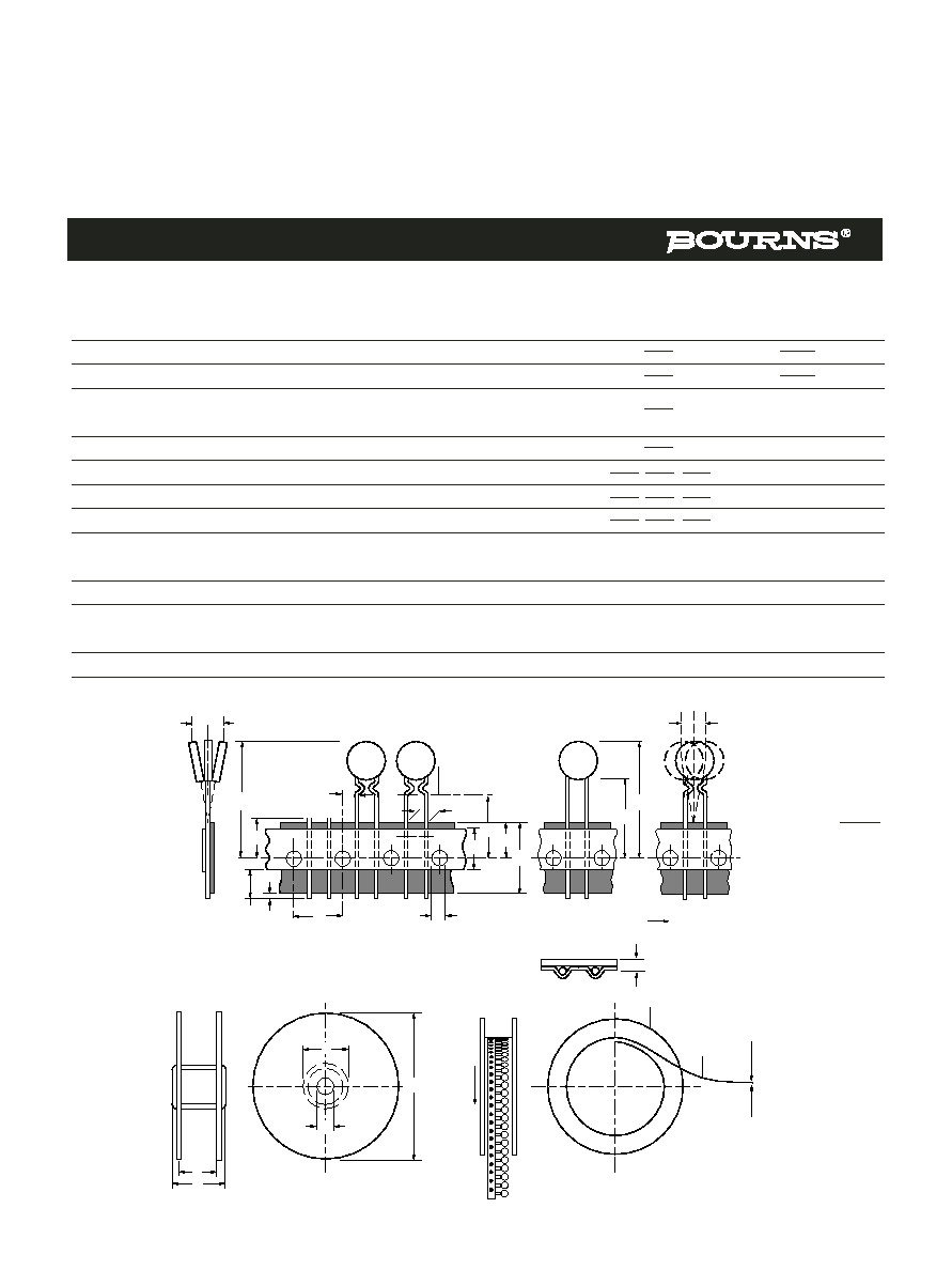
A
B
C (Pitch)
D
E
Physical Characteristics
Model
Max.
Max.
Nom.
Min.
Max.
Style
Lead Dia.
Material
MF-R055/90
10.9
14.0
5.1 � 0.7
6.3
3.6
1
0.81
Sn/Cu
(0.43)
(0.55)
(0.201 � 0.028)
(0.248)
(0.142)
(0.032)
MF-R055/90U
10.3
10.3
5.1 � 0.7
6.3
3.0
1
0.81
Sn/Cu
(0.4)
(0.4)
(0.201 � 0.028)
(0.248)
(0.118)
(0.032)
MF-R075/90
11.9
15.5
5.1 � 0.7
6.3
3.6
1
0.81
Sn/Cu
(0.47)
(0.61)
(0.201 � 0.028)
(0.248)
(0.142)
(0.032)
Product Dimensions
Packaging options:
BULK: 500 pcs. per bag. TAPE & REEL: 1500 pcs. per reel. AMMO-PACK: 1000 pcs. per pack
MF-R/90 Series -
PTC Resettable Fuses
Additional Features
Bulk packaging, tape and reel and Ammo-Pak available on most models
Patents pending
MM
(INCHES)
DIMENSIONS =
A
E
B
D
C
Style 1
Typical Part Marking
Represents total content. Layout may vary.
R055
1220S
MANUFACTURER'S
TRADEMARK
PART
IDENTIFICATION
LOT NO.
(S = CHINA)
DATE CODE
(FIRST DIGIT =
LAST DIGIT OF YEAR;
NEXT THREE DIGITS =
DAY OF YEAR)
How to Order
MF - R 055/90 U - 0 - 99
Multifuse
�
Product
Designator
Series
R = Radial Leaded
Component
Hold Current, Ihold
055, 075 (0.55 Amps - 0.75 Amps)
Max. Voltage, V
Coating
__ = Coated
U = Uncoated
Packaging Options
- 0 = Bulk Packaging
- 2 = Tape and Reel*
- AP = Ammo-Pak*
Lead Free Option
__ = Standard Product
- 99 = Lead Free
*Packaged per EIA486-B
MF-R/90, REV. C, 02/04
Also available with straight leads.

Specifications are subject to change without notice.
Customers should verify actual device performance in their specific applications.
Devices taped using EIA468�B/IEC286-2 standards. See table below and Figures 1 and 2 for details.
IEC
EIA
Dimensions
Dimension Description
Mark
Mark
Dimensions
Tolerance
Carrier tape width
W
W
Hold down tape width: MF-R/600
W4
min.
Hold down tape width: all others
W4
ref.
Hold down tape
W0
No protrusion
Top distance between tape edges
W2
W6
max.
Sprocket hole position
W1
W5
Sprocket hole diameter
D0
D0
Abscissa to plane (straight lead)
H
H
Abscissa to plane (kinked lead)
H0
H0
Abscissa to top
H1
H1
max.
Overall width w/lead protrusion
C1
max.
Overall width w/o lead protrusion
C2
max.
Lead protrusion
I1
L1
max.
Protrusion of cutout
L
L
max.
Protrusion beyond hold tape
I2
I2
Not specified
Sprocket hole pitch
P0
P0
Pitch tolerance
20 consecutive
�1
Device pitch: MF-R005 � MF-R160 & MF-R/90
Device pitch: MF-R185 � MF-R400 & MF-R/600
Device pitch: MF-RX110 � MF-RX160
Device pitch: MF-RX185 � MF-RX375
Device pitch: MF-R/250 & MF-RX/250
Tape thickness
t
t
max.
Tape thickness with splice
t1
max.
Splice sprocket hole alignment
0
Body lateral deviation
h
h
0
Body tape plane deviation
p
p
0
Lead seating plane deviation: MF-R/600*
P1
P1
Lead seating plane deviation
P1
P1
0
Lead spacing
F
F
Reel width
w
w
max.
Reel diameter
d
a
max.
Space between flanges less device
MF-R, MF-RX, MF-R/90, MF-R/250, MF-RX/250 & MF-R/600 Series
Tape and Reel Specifications
18
(.709)
-0.5/+1.0
(-0.02/+.039)
9
(.354)
-0.5/+0.75
(-0.02/+0.03)
4
(.157)
�0.2
(�.0078)
18.5
(.728)
�3.0
(�.118)
16
(.63)
32.2
(1.268)
43.2
(1.7)
42.5
(1.673)
1.0
(.039)
11
(.433)
�0.5
(�.02)
12.7
(0.5)
12.7
(0.5)
12.7
(0.5)
25.4
(1.0)
12.7
(0.5)
12.7
(0.5)
0.9
(.035)
2.0
(.079)
3.81
(.015)
5.08
(0.2)
56
(2.205)
370
(14.57)
�0.3
(�.012)
�0.3
(�.012)
�1.0
(�.039)
�1.3
(�.051)
�0.7
(�.028)
�0.7
(�.028)
�0.8
(�.035)
4.75
(.187)
�3.25
(�.128)
5
(.197)
11
(.433)
3
(.118)
DIMENSIONS =
MM
(INCHES)
*Differs from EIA specification.
MF-R, MF-RX, MF-R/90, MF-R/250, MF-RX/250 & MF-R/600 Series
Tape and Reel Specifications
Specifications are subject to change without notice.
Customers should verify actual device performance in their specific applications.
t
User direction of feed
Cross section A - B
p
p
H
H
1
Reference plane
W
0
H
0
W
1
W
A
B
F
D
0
P
0
I
1
I
2
L
H
1
P
1
h
h
h
w
h
f
d
Reel
Upper side
Tape
Lower side
User
direction
of
feed
Reel Dimensions - Figure 2
Taped Component Dimensions - Figure 1
4.75
(.187)
�3.25
(�.128)
26
(1.024)
80
(3.15)
91
(3.58)
56
(2.2)
372
(14.6)
372
(14.6)
�12.0
(�.472)
DIMENSIONS =
MM
(INCHES)
IEC
EIA
Dimensions
Dimension Description
Mark
Mark
Dimensions
Tolerance
Space between flanges less device
Arbor hole diameter
f
c
Core diameter: MF-R, MF-RX, MF-R/90 & MF-R/250
h
n
max.
Core diameter: MF-RX/250 & MF-R/600
h
n
max.
Box: MF-R, MF-RX, MF-R/90 & MF-R/250
max.
Box: MF-RX/250
max.
Box: MF-R/600
max.
Consecutive missing places:
MF-R, MF-RX, MF-R/90 & MF-R/250
3
max.
Consecutive missing places: MF-RX/250 & MF-R/600
None
Empty places per reel:
MF-R, MF-RX, MF-R/90 & MF-R/250
Not specified
Empty places per reel: MF-RX/250 & MF-R/600
0.1 %
67
(2.64)
372
(14.6)
362
(14.25)
64
(2.52)
372
(14.6)
362
(14.25)