*RoHS Directive 2002/95/EC Jan 27 2003 including Annex.
Specifications are subject to change without notice.
Customers should verify actual device performance in their specific applications.
TC73 - Trimming Potentiometer
Electrical Characteristics
Standard Resistance Range
..................................500 to 1 megohm
(see standard resistance table)
Resistance Tolerance ............±30 % std.
Absolute Minimum Resistance
1K Ohms......................20 ohms max.
>1K Ohms ....................2 % max. of TR
Contact Resistance Variation
...............................................5 % max.
Resolution...................................Infinite
Adjustment Angle.............260 ∞ ±20 ∞(-2)
Environmental Characteristics
Power Rating (50 VDC max.)
50 ∞C ......................................0.05 watt
Temperature Range ......-25 ∞C to +85 ∞C
Temperature Coefficient ....±250 ppm/∞C
Humidity ....................................95 %RH
500 hours
TRS max. ........................+15 % to -2 %
Load Life
............@ 50 ∞C rated power 500 hours
TRS ±5 %
Rotational Cycling......................20 turns
TRS ±20 %
Physical Characteristics
Torque........................10-150 g-cm max.
Mechanical Angle
.......................Continuous; 260 ∞ ± 20 ∞
Marking......................Part marking code
Standard Packaging
..................................2000 pcs./7 " reel
Soldering Process
Hand Soldering ...Soldering Iron of 20 W
or less controlled at 280 ∞C for about
3 sec. while applying solder
Reflow Soldering ........Peak temperature
or reflow oven should be
set to 240 ∞C max.
Features
Recommended for reflow processing
Rotor design compatible with pick and
place and automatic adjustment equipment
Supplied in 8 mm embossed tape,
compatible with automatic assembly
equipment
Carbon element
RoHS compliant* - see
processing
information
on lead free surface mount
trimmers
Standard Resistance Table
Popular distribution resistance values listed in
boldface. Special resistances available.
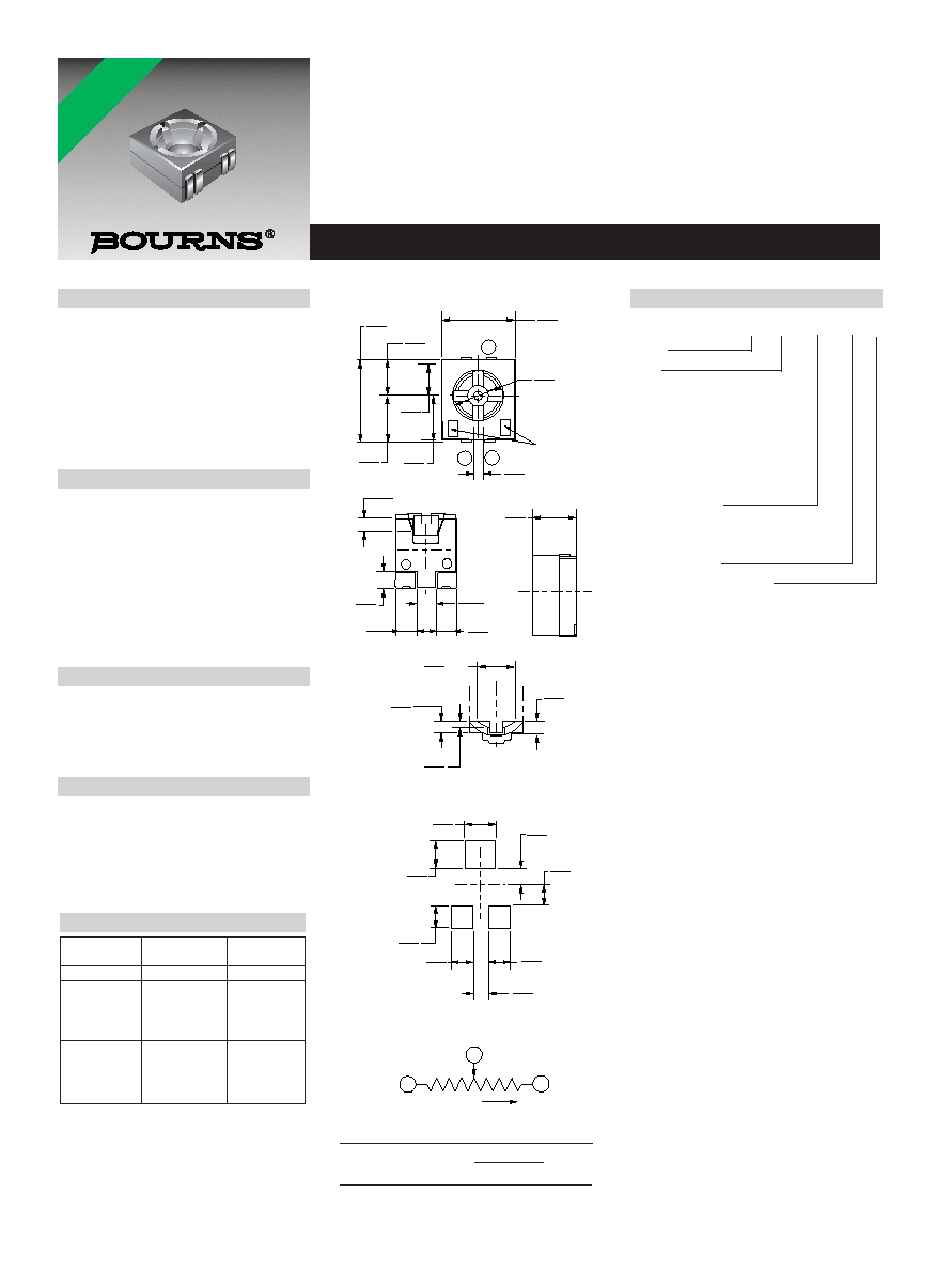
SUGGESTED PCB LAYOUT
2
1
3
0.50
(.019)
2.20
(.086)
TC73X/W-2
1.30
(.051)
0.65
(.025)
3.10
(.122)
1.80
(.070)
1.60
(.062)
3.60
(.141)
1.25
(.049)
1.20
(.047)
1.15
(.059)
0.80
(.031)
RESISTANCE
1.90
(.075)
1.50
(.059)
1.80
(.070)
0.80
(.031)
1.15
(.059)
0.80
(.031)
0.55
(.021)
0.35
(.013)
DRIVER
SLOT DEPTH
0.20
(.008)
1.80
(.070)
DIA.
DRIVER SLOT SHAPE
1.30
(.051)
1.20
(.047)
1.25
(.049)
0.80
(.031)
How To Order
TC73 X - 1 - 103 E
Model
Style
Orientation of Parts
In Tape:
Style X: Terminals Away
From Sprocket
Holes
Style W: Terminals in direction
to sprocket holes
(preferred)
Standard or Modified
Product Indicator
1 = Mechanical rotation stop
(preferred)
2 = Continuous
Resistance Code
Embossed Tape Designator
E = 2000 pcs. per reel, 8 mm tape
Consult factory for other available options.
1
3
CW
CLOCKWISE
CCW
2
WIPER
Resistance
Part Marking
Resistance
(Ohms)
Code
Code
500
52
501
1,000
13
102
2,000
23
202
5,000
53
502
10,000
14
103
20,000
24
203
50,000
54
503
100,000
15
104
200,000
25
204
500,000
55
504
1,000,000
16
105
DIMENSIONS ARE:
MM
(INCHES)
REV. 09/04
*RoHS COMPLIANT