 | –≠–ª–µ–∫—Ç—Ä–æ–Ω–Ω—ã–π –∫–æ–º–ø–æ–Ω–µ–Ω—Ç: PCM1741 | –°–∫–∞—á–∞—Ç—å:  PDF PDF  ZIP ZIP |

+3.3V Single-Supply, 24-Bit, 96kHz Sampling
Enhanced Multilevel, Delta-Sigma, Audio
DIGITAL-TO-ANALOG CONVERTER
PCM1741
DESCRIPTION
The PCM1741 is a CMOS, monolithic, integrated circuit
which includes stereo Digital-to-Analog Converters
(DACs) and support circuitry in a small SSOP-16 package.
The data converters utilize Texas Instrument's enhanced
multilevel delta-sigma architecture that employs fourth-
order noise shaping and 8-level amplitude quantization to
achieve excellent dynamic performance and improved toler-
ance to clock jitter. The PCM1741 accepts industry standard
audio data formats with 16- to 24-bit data, providing easy
interfacing to audio DSP and decoder chips. Sampling rates
up to 100kHz are supported. A full set of user-program-
mable functions are accessible through a 3-wire serial
control port that supports register write functions.
FEATURES
q
24-BIT RESOLUTION
q
ANALOG PERFORMANCE (V
CC
= +3.3V):
Dynamic Range: 98dB typ
SNR: 98dB typ
THD+N: 0.005% typ
Full-Scale Output: 2.05Vp-p typ
q
8x OVERSAMPLING DIGITAL FILTER:
Stopband Attenuation: ≠55dB
Passband Ripple:
±
0.03dB
q
SAMPLING FREQUENCY: 5kHz to 100kHz
q
SYSTEM CLOCK: 256, 384, 512, 768f
S
with
Auto Detect
q
ACCEPTS 16-, 18-, 20-, AND 24-BIT AUDIO
DATA
q
DATA FORMATS: Standard, I
2
S, and Left-
Justified
q
USER-PROGRAMMABLE MODE CONTROLS:
Digital Attenuation: 0dB to ≠63dB, 0.5dB/Step
Digital De-Emphasis
Digital Filter Roll-Off: Sharp or Slow
Soft Mute
Zero Flags for Each Output
q
3.3V SINGLE POWER SUPPLY
q
5V TOLERANT DIGITAL INPUTS
q
SMALL SSOP-16 PACKAGE
www.ti.com
Copyright © 2000, Texas Instruments Incorporated
SBAS175
Printed in U.S.A. December, 2000
APPLICATIONS
q
AV RECEIVERS
q
DVD MOVIE PLAYERS
q
DVD ADD-ON CARDS FOR HIGH-END PCs
q
HDTV RECEIVERS
q
CAR AUDIO SYSTEMS
q
OTHER APPLICATIONS REQUIRING 24-BIT
AUDIO
PCM
174
1
PCM1741
2
SBAS175
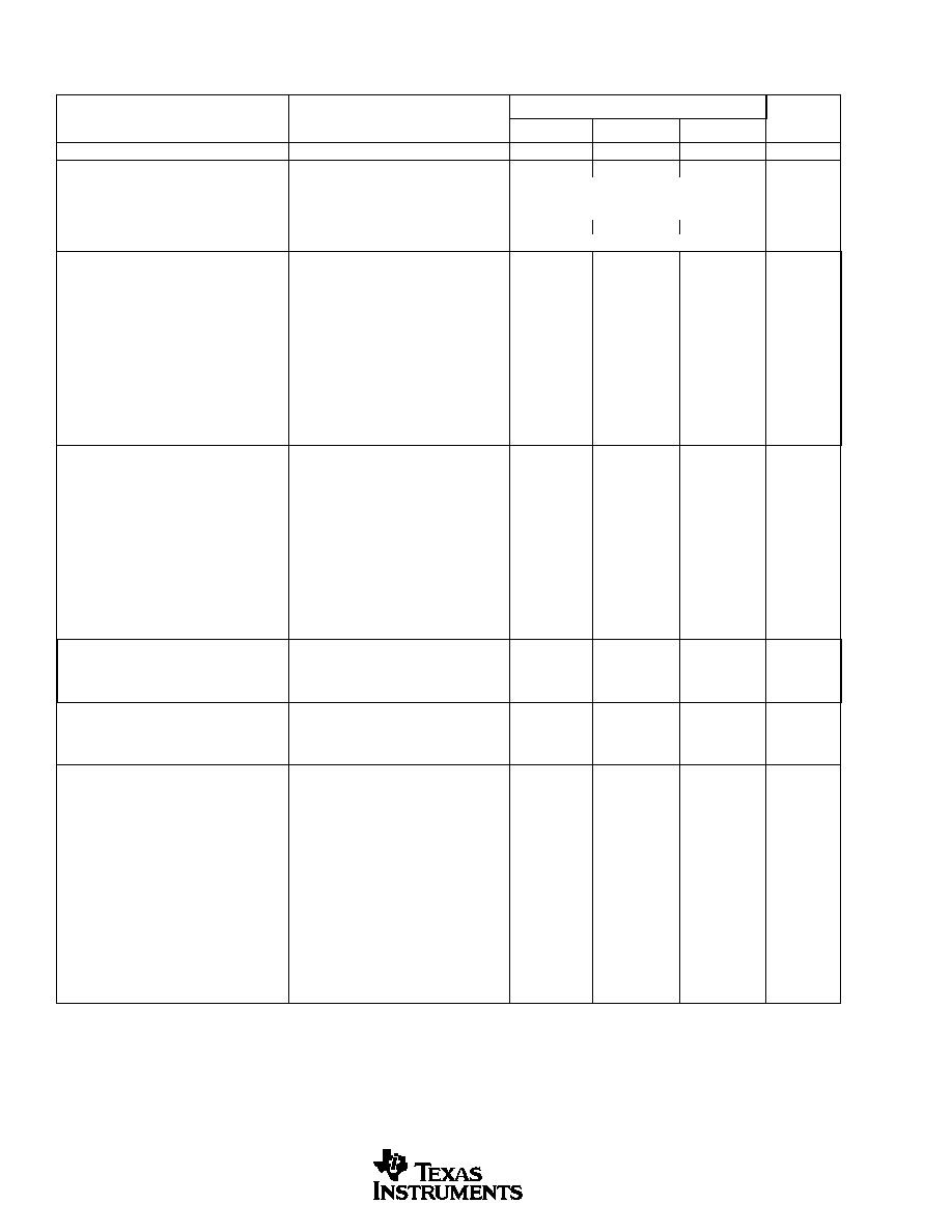
SPECIFICATIONS
All specifications at T
A
= +25
∞
C, V
CC
= 5.0V, V
DD
= 3.3V, f
S
= 44.1kHz, system clock = 384f
S
, and 24-bit data, unless otherwise noted.
PCM1741E
PARAMETER
CONDITIONS
MIN
TYP
MAX
UNITS
RESOLUTION
24
Bits
DATA FORMAT
Audio Data Interface Formats
Standard, I
2
S, Left-Justified
Audio Data Bit Length
16-, 18-, 20-, 24-Bits Selectable
Audio Data Format
MSB-First, Binary Two's Complement
Sampling Frequency (f
S
)
5
100
kHz
System Clock Frequency
256, 384, 512, 768f
S
DIGITAL INPUT/OUTPUT
Logic Family
TTL-Compatible
Input Logic Level
V
IH
2.0
VDC
V
IL
0.8
VDC
Input Logic Current
I
IH
(1)
V
IN
= V
DD
10
µ
A
I
IL
(1)
V
IN
= 0V
≠10
µ
A
I
IH
(2)
V
IN
= V
DD
65
100
µ
A
I
IL
(2)
V
IN
= 0V
≠10
µ
A
Output Logic Level
V
OH
(3)
I
OH
= ≠2mA
2.4
VDC
V
OL
(3)
I
OL
= +2mA
1.0
VDC
DYNAMIC PERFORMANCE
(4)
PCM1741E
THD+N at V
OUT
= 0dB
f
S
= 44.1kHz
0.005
0.01
%
f
S
= 96kHz
0.007
%
THD+N at V
OUT
= ≠60dB
f
S
= 44.1kHz
1.6
%
f
S
= 96kHz
2.0
%
Dynamic Range
EIAJ, A-Weighted, f
S
= 44.1kHz
92
98
dB
A-Weighted, f
S
= 96kHz
96
dB
Signal-to-Noise Ratio
EIAJ, A-Weighted, f
S
= 44.1kHz
92
98
dB
A-Weighted, f
S
= 96kHz
96
dB
Channel Separation
f
S
= 44.1kHz
90
96
dB
f
S
= 96kHz
94
dB
Level Linearity Error
V
OUT
= ≠90dB
±
0.5
dB
DC ACCURACY
Gain Error
±
1.0
±
6
% of FSR
Gain Mismatch, Channel-to-Channel
±
1.0
±
3
% of FSR
Bipolar Zero Error
V
OUT
= 0.5 V
CC
at Bipolar Zero
±
30
±
60
mV
ANALOG OUTPUT
Output Voltage
Full Scale (0dB)
62% of V
CC
Vp-p
Center Voltage
50% of V
CC
VDC
Load Impedance
AC Load
5
k
DIGITAL FILTER PERFORMANCE
Filter Characteristics 1, Sharp Roll-Off
Passband
±
0.03dB
0.454f
S
Passband
≠3dB
0.487f
S
Stopband
0.546f
S
dB
Passband Ripple
±
0.03
dB
Stopband Attenuation
Stopband = 0.546f
S
≠50
dB
Stopband Attenuation
Stopband = 0.567f
S
≠55
Filter Characteristics 2, Slow Roll-Off
Passband
±
0.5dB
0.198f
S
Passband
≠3dB
0.390f
S
Stopband
0.884f
S
Passband Ripple
±
0.5
dB
Stopband Attenuation
Stopband = 0.884f
S
≠40
dB
Delay Time
20/f
S
sec
De-Emphasis Error
±
0.1
dB
PCM1741
3
SBAS175
ANALOG FILTER PERFORMANCE
Frequency Response
f = 20kHz
≠0.03
dB
f = 44kHz
≠0.20
dB
POWER SUPPLY REQUIREMENTS
(4)
Voltage Range, V
DD
+2.7
+3.3
+3.6
VDC
V
CC
+2.7
+3.0
+3.6
VDC
Supply Current, I
DD
f
S
= 44.1kHz
6.0
10
mA
f
S
= 96kHz
13.0
mA
I
CC
f
S
= 44.1kHz
7.0
11
mA
f
S
= 96kHz
7.0
mA
Power Dissipation
f
S
= 44.1kHz
43
88
mW
f
S
= 96kHz
66
mW
TEMPERATURE RANGE
Operation Temperature
≠25
+85
∞
C
Thermal Resistance
JA
SSOP-16
115
∞
C/W
NOTES: (1) Pins 1, 2, 3, 16 (SCK, BCK, LRCK, DATA). (2) Pins 13-15 (MD, MC, ML). (3) Pins 11, 12 (ZEROR, ZEROL). (4) Analog performance specifications
are tested with a Shibasoku #725 THD Meter with 400Hz HPF on, 30kHz LPF on, and an average mode with 20kHz bandwidth limiting. The load connected
to the analog output is 5k
or larger, via capacitive coupling.
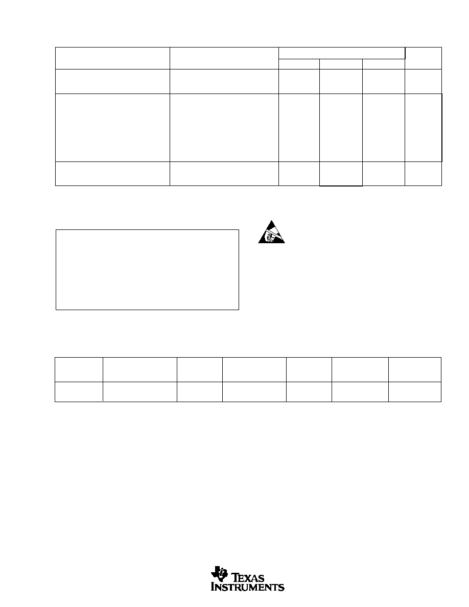
SPECIFICATIONS
(Cont.)
All specifications at T
A
= +25
∞
C, V
CC
= 5.0V, V
DD
= 3.3V, system clock = 384f
S
(f
S
= 44.1kHz), and 24-bit data, unless otherwise noted.
PCM1741E
PARAMETER
CONDITIONS
MIN
TYP
MAX
UNITS
ELECTROSTATIC
DISCHARGE SENSITIVITY
This integrated circuit can be damaged by ESD. Burr-Brown
recommends that all integrated circuits be handled with
appropriate precautions. Failure to observe proper handling
and installation procedures can cause damage.
ESD damage can range from subtle performance degradation
to complete device failure. Precision integrated circuits may
be more susceptible to damage because very small parametric
changes could cause the device not to meet its published
specifications.
Power Supply Voltage, V
DD
.............................................................. +4.0V
V
CC
.............................................................. +6.5V
Ground Voltage Differences ..............................................................
±
0.1V
Digital Input Voltage ................................................ ≠0.3V to (6.5V + 0.3V)
Input Current (except power supply) ...............................................
±
10mA
Ambient Temperature Under Bias .................................. ≠40
∞
C to +125
∞
C
Storage Temperature ...................................................... ≠55
∞
C to +150
∞
C
Junction Temperature .................................................................... +150
∞
C
Lead Temperature (soldering, 5s) ................................................. +260
∞
C
Package Temperature (IR reflow, 10s) .......................................... +235
∞
C
ABSOLUTE MAXIMUM RATINGS
PACKAGE
SPECIFIED
DRAWING
TEMPERATURE
PACKAGE
ORDERING
TRANSPORT
PRODUCT
PACKAGE
NUMBER
RANGE
MARKING
NUMBER
(1)
MEDIA
PCM1741E
SSOP-16
322
≠25
∞
C to +85
∞
C
PCM1741E
PCM1741E
Rails
"
"
"
"
"
PCM1741E/2K
Tape and Reel
NOTE: (1) Models with a slash (/) are available only in Tape and Reel in the quantities indicated (e.g., /2K indicates 2000 devices per reel). Ordering 2000 pieces
of "PCM1741E/2K" will yield a single 2000-piece Tape and Reel.
PACKAGE/ORDERING INFORMATION
PCM1741
4
SBAS175
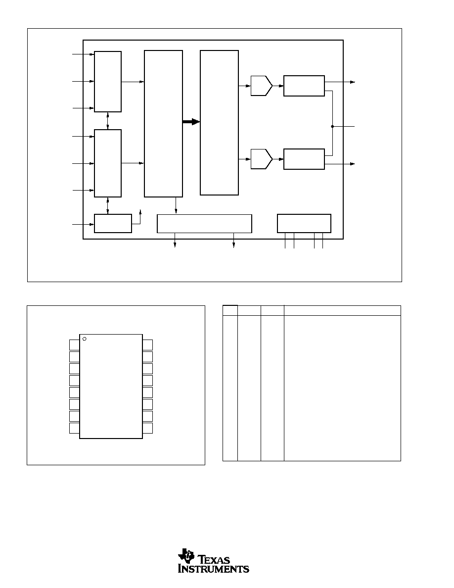
BLOCK DIAGRAM
PIN ASSIGNMENTS
PIN
NAME
TYPE
FUNCTION
1
BCK
IN
Audio Data Bit Clock Input.
(1)
2
DATA
IN
Audio Data Digital Input.
(1)
3
LRCK
IN
L-Channel and R-Channel Audio Data Latch En-
able Input.
(1)
4
DGND
≠
Digital Ground
5
V
DD
≠
Digital Power Supply, +3.3V
6
V
CC
≠
Analog Power Supply, +3.3V
7
V
OUT
L
OUT
Analog Output for L-Channel.
8
V
OUT
R
OUT
Analog Output for R-Channel.
9
AGND
≠
Analog Ground
10
V
COM
≠
Common Voltage Decoupling.
11
ZEROR/
OUT
Zero Flag Output for R-Channel/Zero Flag Output
ZEROA
for L/R-Channel.
12
ZEROL/NA
OUT
Zero Flag Output for L-Channel/No Assign.
13
MD
IN
Mode Control Data Input.
(2)
14
MC
IN
Mode Control Clock Input.
(2)
15
ML
IN
Mode Control Latch Input.
(2)
16
SCK
IN
System Clock Input.
NOTES: (1) Schmitt-trigger input, 5V tolerant. (2) Schmitt-trigger with internal
pull-down, 5V tolerant.
PIN CONFIGURATION
TOP VIEW
SSOP
Audio
Serial
Port
Output Amp and
Low-Pass Filter
DAC
8x
Oversampling
Digital Filter
with
Function
Controller
Enhanced
Multilevel
Delta-Sigma
Modulator
Output Amp and
Low-Pass Filter
DAC
BCK
LRCK
DATA
ML
MC
MD
Serial
Control
Port
System Clock
Manager
Zero Detect
Power Supply
V
OUT
L
V
COM
V
OUT
R
V
DD
DGND
ZEROL
ZEROR
SCK
System Clock
V
CC
AGND
BCK
DATA
LRCK
DGND
V
DD
V
CC
V
OUT
L
V
OUT
R
SCK
ML
MC
MD
ZEROL/NA
ZEROR/ZEROA
V
COM
AGND
1
2
3
4
5
6
7
8
16
15
14
13
12
11
10
9
PCM1741
PCM1741
5
SBAS175
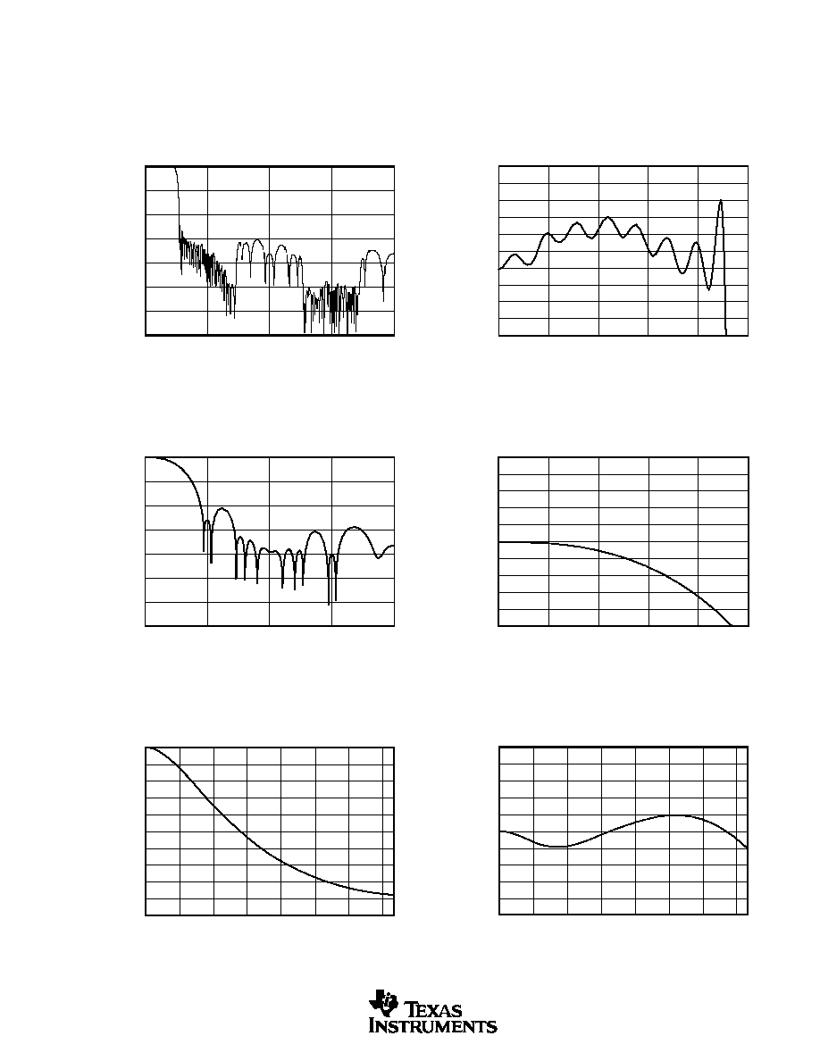
TYPICAL PERFORMANCE CURVES
All specifications at T
A
= +25
∞
C, V
CC
= V
DD
= 3.3V, system clock = 384f
S
(f
S
= 44.1kHz), and 24-bit input data, unless otherwise noted.
DIGITAL FILTER
Digital Filter (De-Emphasis Off
5
4
3
2
1
0
≠1
≠2
≠3
≠4
≠5
TRANSITION CHARACTERISTICS (Slow Roll-Off)
0
0.1
0.2
0.3
0.4
0.5
Frequency (x f
S
)
Amplitude (dB)
0
≠20
≠40
≠60
≠80
≠100
≠120
≠140
FREQUENCY RESPONSE (Sharp Roll-Off)
0
1
2
3
4
Frequency (x f
S
)
Amplitude (dB)
0.05
0.04
0.03
0.02
0.01
0
≠0.01
≠0.02
≠0.03
≠0.04
≠0.05
FREQUENCY RESPONSE PASSBAND
(Sharp Roll-Off)
0
0.1
0.2
0.3
0.4
0.5
Frequency (x f
S
)
Amplitude (dB)
0
≠20
≠40
≠60
≠80
≠100
≠120
≠140
FREQUENCY RESPONSE (Slow Roll-Off)
0
1
2
3
4
Frequency (x f
S
)
Amplitude (dB)
De-Emphasis
0.0
≠1.0
≠2.0
≠3.0
≠4.0
≠5.0
≠6.0
≠7.0
≠8.0
≠9.0
≠10.0
DE-EMPHASIS (f
S
= 32kHz)
0
2
4
6
8
10
12
14
Frequency (kHz)
Level (dB)
0.5
0.4
0.3
0.2
0.1
0.0
≠0.1
≠0.2
≠0.3
≠0.4
≠0.5
DE-EMPHASIS ERROR (f
S
= 32kHz)
0
2
4
6
8
10
12
14
Frequency (kHz)
Error (dB)