
A
5 to 6 Watt HW Dual Series DC/DC Converters
2401 Stanwell Drive ∑ Concord, California 94520 ∑ Ph: 925/687-4411 or 800/542-3355 ∑ Fax: 925/687-3333 ∑ www.calex.com ∑ Email: sales@calex.com
1
8/07/2003, eco# 041007-1, eco# 050210-1 , eco# 060306-4, 060406-2, 060612-1
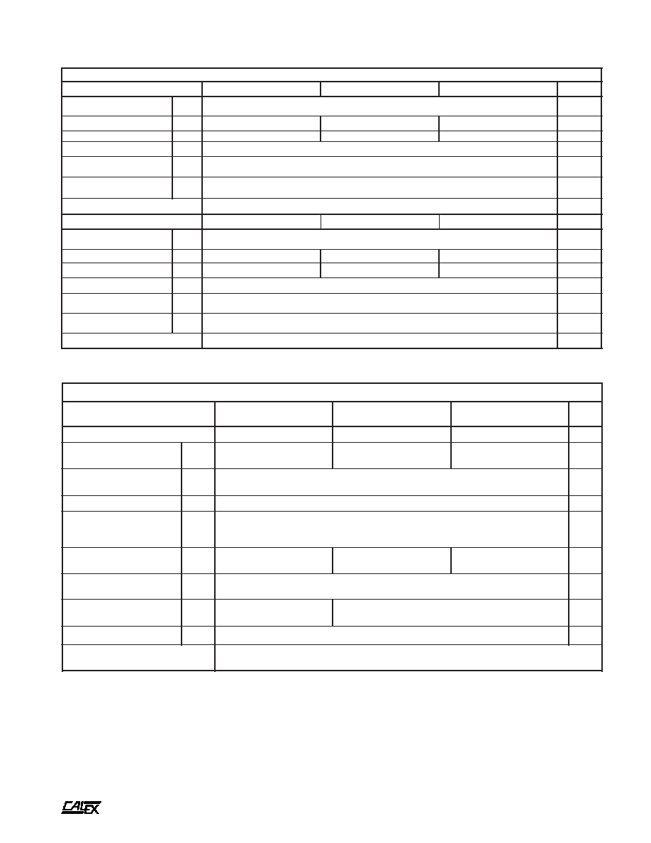
5 to 6 Watt Dual HW Series Block Diagram
Features
4:1 Input Voltage Range
Internal Input Filter
Industry Standard Pinout
Isolation Voltage to 1544 VDC
Water Washable Case Design
t
r
a
h
C
n
o
i
t
c
e
l
e
S
l
e
d
o
M
e
g
n
a
R
t
u
p
n
I
C
D
V
t
u
p
t
u
O
C
D
V
t
u
p
t
u
O
A
m
n
i
M
x
a
M
W
H
0
0
5
.
5
D
4
2
9
6
3
5
±
0
0
5
W
H
0
5
2
.
2
1
D
4
2
9
6
3
2
1
±
0
5
2
W
H
0
0
2
.
5
1
D
4
2
9
6
3
5
1
±
0
0
2
W
H
0
0
5
.
5
D
8
4
8
1
5
7
5
±
0
0
5
W
H
0
5
2
.
2
1
D
8
4
8
1
5
7
2
1
±
0
5
2
W
H
0
0
2
.
5
1
D
8
4
8
1
5
7
5
1
±
0
0
2
Description
These 5 Watt DC/DC Converters were designed for fast
integration with your systems power needs. The 5 Watt HW
Duals are ideal for battery operated industrial, medical control
and remote data collection systems.
A
5 to 6 Watt HW Dual Series DC/DC Converters
2401 Stanwell Drive ∑ Concord, California 94520 ∑ Ph: 925/687-4411 or 800/542-3355 ∑ Fax: 925/687-3333 ∑ www.calex.com ∑ Email: sales@calex.com
2
8/07/2003, eco# 041007-1, eco# 050210-1 , eco# 060306-4, 060406-2, 060612-1
s
r
e
t
e
m
a
r
a
P
t
u
p
n
I
l
e
d
o
M
W
H
0
0
5
.
5
D
4
2
W
H
0
5
2
.
2
1
D
4
2
W
H
0
0
2
.
5
1
D
4
2
s
t
i
n
U
)
1
(
e
g
n
a
R
e
g
a
t
l
o
V
N
I
M
X
A
M
9
6
3
C
D
V
d
a
o
L
ll
u
F
,
t
n
e
r
r
u
C
t
u
p
n
I
X
A
M
8
7
2
2
1
3
2
1
3
A
m
y
c
n
e
i
c
i
f
f
E
P
Y
T
5
7
0
8
0
8
%
y
c
n
e
u
q
e
r
F
g
n
i
h
c
t
i
w
S
P
Y
T
0
0
4
z
H
k
,
e
g
a
t
l
o
v
r
e
v
O
t
u
p
n
I
m
u
m
i
x
a
M
m
u
m
i
x
a
M
s
m
0
0
1
X
A
M
0
4
C
D
V
,
e
m
i
T
n
o
-
n
r
u
T
r
o
r
r
E
t
u
p
t
u
O
%
1
P
Y
T
5
4
s
m
e
s
u
F
d
e
d
n
e
m
m
o
c
e
R
)
3
(
S
P
M
A
l
e
d
o
M
W
H
0
0
5
.
5
D
8
4
W
H
0
5
2
.
2
1
D
8
4
W
H
0
0
2
.
5
1
D
8
4
s
t
i
n
U
)
1
(
e
g
n
a
R
e
g
a
t
l
o
V
N
I
M
X
A
M
8
1
5
7
C
D
V
d
a
o
L
ll
u
F
,
t
n
e
r
r
u
C
t
u
p
n
I
X
A
M
8
2
1
0
5
1
0
5
1
A
m
y
c
n
e
i
c
i
f
f
E
P
Y
T
1
8
3
8
3
8
%
y
c
n
e
u
q
e
r
F
g
n
i
h
c
t
i
w
S
P
Y
T
0
0
4
z
H
k
,
e
g
a
t
l
o
v
r
e
v
O
t
u
p
n
I
m
u
m
i
x
a
M
m
u
m
i
x
a
M
s
m
0
0
1
X
A
M
0
8
C
D
V
,
e
m
i
T
n
o
-
n
r
u
T
r
o
r
r
E
t
u
p
t
u
O
%
1
P
Y
T
5
4
s
m
e
s
u
F
d
e
d
n
e
m
m
o
c
e
R
)
3
(
S
P
M
A
s
r
e
t
e
m
a
r
a
P
t
u
p
t
u
O
l
e
d
o
M
W
H
0
0
5
.
5
D
4
2
W
H
0
0
5
.
5
D
8
4
W
H
0
5
2
.
2
1
D
4
2
W
H
0
5
2
.
2
1
D
8
4
W
H
0
0
2
.
5
1
D
4
2
W
H
0
0
2
.
5
1
D
8
4
s
t
i
n
U
e
g
a
tl
o
V
t
u
p
t
u
O
5
±
2
1
±
5
1
±
C
D
V
)
5
(
e
g
n
a
R
d
a
o
L
d
e
t
a
R
N
I
M
X
A
M
0
0
1
±
0
0
5
±
0
6
±
0
5
2
±
0
5
±
0
0
2
±
A
m
y
c
a
r
u
c
c
A
t
n
i
o
p
t
e
S
l
a
it
i
n
I
P
Y
T
X
A
M
1
±
3
±
%
e
c
n
a
l
a
B
t
u
p
t
u
O
P
Y
T
1
±
%
,
n
o
it
a
l
u
g
e
R
d
a
o
L
m
o
r
f
d
e
g
n
a
h
c
s
d
a
o
L
h
t
o
B
)
5
(
d
a
o
l
n
i
M
o
t
x
a
M
P
Y
T
1
%
d
a
o
L
e
n
O
,
n
o
it
a
l
u
g
e
R
s
s
o
r
C
n
i
M
t
a
P
Y
T
4
2
2
%
n
o
it
a
l
u
g
e
R
e
n
i
L
n
i
M
o
t
x
a
M
=
n
i
V
P
Y
T
5
.
0
%
)
2
(
w
b
z
H
m
0
2
,
e
s
i
o
N
P
Y
T
t
u
p
t
u
O
f
o
%
5
.
1
t
u
p
t
u
O
f
o
%
1
V
m
P
-
P
)
4
(
t
n
e
i
c
if
f
e
o
C
e
r
u
t
a
r
e
p
m
e
T
P
Y
T
0
0
1
C
∞
/
m
p
p
N
M
C
o
t
t
i
u
c
r
i
C
t
r
o
h
S
n
i
V
l
a
n
i
m
o
N
t
r
a
t
s
e
R
o
t
u
A
s
u
o
u
n
it
n
o
C

A
5 to 6 Watt HW Dual Series DC/DC Converters
2401 Stanwell Drive ∑ Concord, California 94520 ∑ Ph: 925/687-4411 or 800/542-3355 ∑ Fax: 925/687-3333 ∑ www.calex.com ∑ Email: sales@calex.com
3
8/07/2003, eco# 041007-1, eco# 050210-1 , eco# 060306-4, 060406-2, 060612-1
Mechanical tolerances unless otherwise noted:
X.XX dimensions: ±0.030 inches
X.XXX dimensions: ±0.005 inches
All dimensions in inches.
NOTES:
(1)
All parameters measured at Tc=25∞C, nominal input voltage
and full rated load unless otherwise noted. Refer to the
CALEX Application Notes for the definition of terms.
(2)
Output Noise is measured with a 1µF tantalum capacitor and a
0.01µF ceramic capacitor across the output. The fundamental
component of noise is at the switching frequency and also is
commonly referred to as ripple.
(3)
External fusing should be used for system protection due to a
catastrophic failure. See CALEX Application Note 9 in the Calex
DC/DC Catalog to determine correct fuse.
(4)
Temperature coefficient is defined for case temperatures. Output
voltage deviation is calculated as the maximum resulting from
either 1) 25∞C case to maximum operating case temperature, or
2) 25∞C case to minimum operating case temperature.
(5)
Below the minimum rated load, the output may exhibit noise
performance degradation. Operation with less than minimum
rated load will not damage the unit, and the DC regulation is not
significantly affected.
(6)
The case thermal impedance is specified and the case
temperature rise over ambient per package watt dissipated.
(7)
Specifications subject to change without notice.
(8)
Water Washability - Calex DC/DC converters are designed to
withstand most solder/wash processes. Careful attention should
be used when assessing the applicability in your specific
manufacturing process. Converters are not hermetically sealed.
(9)
External Input Capacitance:
The HW Dual Series requires an external input capacitor for
proper operation. Operation of this converter without an external
input capacitor may cause damage to the converter. A capacitor
equivalent to, or larger that a 22uF electrolytic capacitor should
be used.
(10) External Output Capacitance:
The maximum external output capacitance per output is
200uF.
Mechanical Outline and
Connector Pin Assignments
s
n
o
i
t
a
c
i
f
i
c
e
p
S
l
a
r
e
n
e
G
s
l
e
d
o
M
l
l
A
s
t
i
n
U
n
o
i
t
a
l
o
s
I
e
g
a
tl
o
V
n
o
it
a
l
o
s
I
t
u
p
t
u
O
r
e
h
ti
E
o
t
t
u
p
n
I
N
I
M
4
4
5
1
C
D
V
t
u
p
t
u
O
o
t
t
u
p
n
I
e
c
n
a
ti
c
a
p
a
C
P
Y
T
0
3
F
p
l
a
t
n
e
m
n
o
r
i
v
n
E
e
g
n
a
R
g
n
it
a
r
e
p
O
e
s
a
C
N
I
M
X
A
M
0
4
-
0
0
1
+
C
∞
e
g
n
a
R
e
g
a
r
o
t
S
N
I
M
X
A
M
0
4
-
0
1
1
+
C
∞
)
6
(
e
c
n
a
d
e
p
m
I
l
a
m
r
e
h
T
P
Y
T
0
3
t
t
a
W
/
C
∞
l
a
r
e
n
e
G
t
h
g
i
e
W
ti
n
U
P
Y
T
5
.
0
z
o
n
o
i
s
n
e
m
i
D
e
s
a
C
"
0
4
.
0
x
"
5
2
.
1
x
"
0
8
.
0
g
n
i
d
n
e
P
s
l
a
v
o
r
p
p
A
y
c
n
e
g
A
0
5
9
0
6
L
U
C
/
L
U
n
i
P
n
o
i
t
c
n
u
F
3
,
2
T
U
P
N
I
-
6
1
,
9
N
M
C
T
U
P
T
U
O
1
1
T
U
P
T
U
O
-
4
1
T
U
P
T
U
O
+
3
2
,
2
2
T
U
P
N
I
+