
A
25 to 30 Watt XW Single Series DC/DC Converters
Manufacturing Company, Inc. ∑ Concord, California 94520 ∑ Ph: 925/687-4411 or 800/542-3355 ∑ Fax: 925/687-3333 ∑ www.calex.com ∑ Email: sales@calex.com
1
eco# 041007-1
25 - 30 Watt XW Single Series Block Diagram
Features
4:1 Input Voltage Range
Low Noise, Highly Regulated Output
Efficiencies to 84% at Full Load
No Derating to 80∞C Case Temperature
Six-Sided Continuous Shielded, Low Thermal
Gradient Copper Case
500 VDC Minimum Input To Output Isolation
Overvoltage Protection for Input and Outputs
Direct Output Paralleling for Added Power
Five Year Warranty
Description
These single output DC/DC converters are designed for wide
input range low noise telecommunications, industrial control
and instrument applications. The ultra wide input range (4:1)
is ideal for battery or solar based applications.
The converters are state-of-the-art 75kHz MOSFET based
designs that provide outstanding efficiencies up to 84 percent
at full load.
The output is regulated with a high loop gain feedback
control method that provides linear regulator type performance
with a true, high efficiency switching DC/DC topology. The
large amount of loop gain insures excellent input ripple
rejection and line transient response.
Outstanding line and load regulation are achieved over the
full input voltage range and over the specified load current
range.
Also included is a logic (open collector TTL / CMOS
compatible) shutdown pin to control converter operation.
The XW Single Series is protected from output shorts to
common by a high speed pulse by pulse digital current limit
circuit and a resettable thermal shut down circuit.
The output and the power switch are overvoltage protected.
t
r
a
h
C
n
o
i
t
c
e
l
e
S
l
e
d
o
M
e
g
n
a
R
t
u
p
n
I
C
D
V
t
u
p
t
u
O
C
D
V
t
u
p
t
u
O
A
m
N
I
M
X
A
M
W
X
0
0
0
5
.
5
S
4
2
0
.
9
0
.
6
3
0
.
5
0
0
0
5
W
X
0
0
5
2
.
2
1
S
4
2
0
.
9
0
.
6
3
0
.
2
1
0
0
5
2
W
X
0
0
0
2
.
5
1
S
4
2
0
.
9
0
.
6
3
0
.
5
1
0
0
0
2
W
X
0
0
0
5
.
5
S
8
4
0
.
0
2
0
.
2
7
0
.
5
0
0
0
5
W
X
0
0
5
2
.
2
1
S
8
4
0
.
0
2
0
.
2
7
0
.
2
1
0
0
5
2
W
X
0
0
0
2
.
5
1
S
8
4
0
.
0
2
0
.
2
7
0
.
5
1
0
0
0
2
DOUBLE SHIELDED
ISOLATION TRANSFORMER
LC
INPUT
FILTER
VOLTAGE
FEED
FORWARD
PWM
FEEDBACK
AMPLIFIER
SIX-SIDED SHIELDED
COPPER CASE
LOW TC
BANDGAP
REFERENCE
THERMAL SHUTDOWN
1.5 MEG || 0.01 µF
C1
C2
D1
1
2
8
+ INPUT
- INPUT
ON/OFF
6
7
4
+ OUTPUT
CMN
TRIM
3 + SENSE
5 - SENSE
10 W
10 W
t
u
p
t
u
O
1
C
2
C
1
D
5
0
0
0
1
F
µ
F
µ
8
6
V
8
.
6
2
1
F
µ
0
3
3
F
µ
7
4
V
5
1
5
1
F
µ
0
3
3
F
µ
7
4
V
8
1

A
25 to 30 Watt XW Single Series DC/DC Converters
Manufacturing Company, Inc. ∑ Concord, California 94520 ∑ Ph: 925/687-4411 or 800/542-3355 ∑ Fax: 925/687-3333 ∑ www.calex.com ∑ Email: sales@calex.com
2
eco# 041007-1
NOTES:
*
All parameters measured at Tc=25∞C, nominal input voltage
and full rated load unless otherwise noted. Refer to the
CALEX Application Notes for the definition of terms,
measurement circuits and other information.
(2)
Determine the correct fuse size by calculating the maximum DC
current drain at low line input , maximum load(or use the supplied
curves) and then adding 20 to 25 percent to get the desired fuse
size.
(3)
Short term stability is specified after a 30 minute warm-up at full
load.
(4)
Transient response is defined as the time for the output to settle
from a 25 to 75 % step load change to a 1% error band (rise time
of step = 2µ Sec).
(5)
Dynamic response is defined as the peak overshoot during a
transient as defined in note 4 above.
(6)
The input ripple rejection is specified for DC to 120 Hz ripple with
a modulation amplitude of 1% of Vin.
(7)
For module protection only, see also note 2.
(8)
The user must not let the output at the pins exceed this voltage
due to the combined effects of line drops and output trim.
(9)
The logic shutdown pin is Open Collector TTL, CMOS, and relay
compatible. The input to this pin is referenced to input (pin 2) and
is protected to +100 VDC.
(10) The functional temperature range is intended to give an additional
data point for use in evaluating this power supply. At the low
functional temperature the power supply will function with no
side effects, however, sustained operation at the high functional
temperature will reduce expected operational life. The data
sheet specifications are not guaranteed over the functional
temperature range.
(11) The case thermal impedance is specified as the case temperature
rise over ambient per package watt dissipated.
(12) Water Washability - Calex DC/DC converters are designed to
withstand most solder/wash processes. Careful attention should
be used when assessing the applicability in your specific
manufacturing process. Converters are not hermetically sealed.
*
s
r
e
t
e
m
a
r
a
P
t
u
p
t
u
O
l
e
d
o
M
W
X
0
0
0
5
.
5
S
4
2
W
X
0
0
0
5
.
5
S
8
4
W
X
0
0
5
2
.
2
1
S
4
2
W
X
0
0
5
2
.
2
1
S
8
4
W
X
0
0
0
2
.
5
1
S
4
2
W
X
0
0
0
2
.
5
1
S
8
4
s
t
i
n
U
e
g
a
t
l
o
V
t
u
p
t
u
O
5
2
1
5
1
C
D
V
t
n
e
r
r
u
C
d
e
t
a
R
N
I
M
X
A
M
0
0
0
0
5
0
0
0
5
2
0
0
0
0
2
A
m
e
g
n
a
R
e
g
a
t
l
o
V
d
a
o
L
%
0
0
1
N
I
M
P
Y
T
X
A
M
5
9
.
4
0
0
.
5
5
0
.
5
0
9
.
1
1
0
0
.
2
1
0
1
.
2
1
0
9
.
4
1
0
0
.
5
1
0
1
.
5
1
C
D
V
d
a
o
L
%
0
0
1
-
0
n
o
i
t
a
l
u
g
e
R
d
a
o
L
P
Y
T
X
A
M
5
0
.
0
0
5
.
0
%
n
o
i
t
a
l
u
g
e
R
e
n
i
L
C
D
V
x
a
M
-
n
i
M
=
n
i
V
P
Y
T
X
A
M
5
0
.
0
0
5
.
0
%
)
3
(
y
t
il
i
b
a
t
S
m
r
e
T
t
r
o
h
S
P
Y
T
2
0
.
0
%
y
t
il
i
b
a
t
S
m
r
e
T
g
n
o
L
P
Y
T
0
2
.
0
s
r
H
k
/
%
)
4
(
e
s
n
o
p
s
e
R
t
n
e
i
s
n
a
r
T
P
Y
T
0
5
0
0
1
0
4
0
0
2
0
4
0
0
2
s
µ
)
5
(
e
s
n
o
p
s
e
R
c
i
m
a
n
y
D
P
Y
T
0
5
2
0
7
2
0
5
1
0
5
2
0
5
1
0
0
2
k
a
e
p
V
m
)
6
(
n
o
i
t
c
e
j
e
R
e
l
p
p
i
R
t
u
p
n
I
P
Y
T
5
7
B
d
w
b
z
H
M
0
2
-
0
,
e
s
i
o
N
P
Y
T
X
A
M
0
1
0
5
0
2
0
5
0
2
0
5
P
-
P
V
m
t
n
e
i
c
i
f
f
e
o
C
e
r
u
t
a
r
e
p
m
e
T
P
Y
T
X
A
M
0
5
0
0
2
0
0
1
0
0
2
0
0
1
0
0
2
C
∞
/
m
p
p
)
7
(
p
m
a
l
C
e
g
a
t
l
o
v
r
e
v
O
P
Y
T
8
.
6
5
1
8
1
C
D
V
n
e
e
w
t
e
B
e
g
a
t
l
o
V
e
l
b
a
w
o
ll
A
m
u
m
i
x
a
M
)
8
(
7
d
n
a
6
s
n
i
P
X
A
M
3
.
6
4
1
7
1
C
D
V
o
t
n
o
i
t
c
e
t
o
r
P
t
i
u
c
r
i
C
t
r
o
h
S
s
t
u
p
t
u
O
ll
a
r
o
f
n
o
m
m
o
C
d
a
o
l
r
e
v
O
l
a
m
r
e
h
T
d
n
a
t
i
m
i
L
t
n
e
r
r
u
C
m
u
m
i
n
i
M
s
r
u
o
H
8
,
s
u
o
u
n
i
t
n
o
C
*
s
r
e
t
e
m
a
r
a
P
t
u
p
n
I
l
e
d
o
M
W
X
0
0
0
5
.
5
S
4
2
W
X
0
0
5
2
.
2
1
S
4
2
W
X
0
0
0
2
.
5
1
S
4
2
W
X
0
0
0
5
.
5
S
8
4
W
X
0
0
5
2
.
2
1
S
8
4
W
X
0
0
0
2
.
5
1
S
8
4
s
t
i
n
U
e
g
n
a
R
e
g
a
t
l
o
V
N
I
M
X
A
M
0
.
9
0
.
6
3
0
.
0
2
0
.
2
7
C
D
V
e
l
p
p
i
R
d
e
t
c
e
l
f
e
R
w
b
z
H
M
0
2
-
0
P
Y
T
X
A
M
5
3
0
0
1
0
4
0
0
1
0
4
0
0
1
0
2
0
4
0
2
0
4
0
2
0
4
P
-
P
A
m
d
a
o
L
ll
u
F
t
n
e
r
r
u
C
t
u
p
n
I
d
a
o
L
o
N
P
Y
T
-
P
Y
T
S
M
R
0
2
3
1
5
1
0
4
5
1
5
2
0
1
5
1
5
2
0
5
6
0
2
0
6
7
0
2
5
4
7
0
2
A
m
y
c
n
e
i
c
i
f
f
E
P
Y
T
9
7
1
8
3
8
0
8
2
8
4
8
%
y
c
n
e
u
q
e
r
F
g
n
i
h
c
t
i
w
S
P
Y
T
5
7
z
H
k
t
u
p
n
I
m
u
m
i
x
a
M
,
e
g
a
t
l
o
v
r
e
v
O
e
g
a
m
a
D
o
N
s
m
0
0
1
X
A
M
0
4
0
8
C
D
V
t
u
o
k
c
o
L
e
g
a
t
l
o
v
r
e
d
n
U
P
Y
T
5
.
8
0
.
8
1
C
D
V
,
e
m
i
T
n
o
-
n
r
u
T
r
o
r
r
E
t
u
p
t
u
O
%
1
P
Y
T
0
3
s
m
e
s
u
F
d
e
d
n
e
m
m
o
c
e
R
)
2
(
e
p
y
T
w
o
l
B
w
o
l
S

A
25 to 30 Watt XW Single Series DC/DC Converters
Manufacturing Company, Inc. ∑ Concord, California 94520 ∑ Ph: 925/687-4411 or 800/542-3355 ∑ Fax: 925/687-3333 ∑ www.calex.com ∑ Email: sales@calex.com
3
eco# 041007-1
n
i
P
n
o
i
t
c
n
u
F
1
T
U
P
N
I
+
2
T
U
P
N
I
-
3
E
S
N
E
S
+
4
M
I
R
T
T
U
P
T
U
O
5
E
S
N
E
S
-
6
T
U
P
T
U
O
+
7
N
M
C
8
F
F
O
/
N
O
If the sense leads are not used they must be connected to their
respective output pins (i.e. Pin 3 to Pin 6 and Pin 5 to Pin 7).
Either a fixed resistor or a trimpot can be used for adjusting
the output voltage as shown in Figure 1.
The XW Single Output Series can be directly paralleled for
higher output current. The circuit shown in Figure 2 results in
output currents that differ by less than 10% between the two
units. With the addition of an OPAMP active trim as shown in
Figure 3, the current sharing will be as good as the match
between the current sense resistors. A minimum load of
100mA should be used with these circuits.
Figure 1. CONNECTIONS FOR OUTPUT TRIM
Mechanical tolerances unless otherwise noted:
X.XX dimensions: ±0.020 inches
X.XXX dimensions: ±0.005 inches
Seal around terminals is not hermetic. Do not immerse units in any
liquid.
Figure 2. SIMPLE PARALLEL CIRCUIT
Figure 3. OPTIMUM PARALLEL CIRCUIT
*
s
n
o
i
t
a
c
i
f
i
c
e
p
S
l
a
r
e
n
e
G
s
l
e
d
o
M
l
l
A
s
t
i
n
U
)
9
(
n
o
i
t
c
n
u
F
F
F
O
/
N
O
l
e
v
e
L
c
i
g
o
L
N
O
n
e
p
O
n
i
P
e
v
a
e
L
r
o
N
I
M
5
.
5
C
D
V
l
e
v
e
L
c
i
g
o
L
F
F
O
X
A
M
8
.
0
C
D
V
e
c
n
a
t
s
i
s
e
R
t
u
p
n
I
P
Y
T
0
0
1
s
m
h
o
k
,
t
n
e
r
r
u
C
e
l
d
I
r
e
t
r
e
v
n
o
C
w
o
L
n
i
P
n
w
o
D
t
u
h
S
P
Y
T
5
A
m
n
o
i
t
a
l
o
s
I
e
g
a
t
l
o
V
n
o
i
t
a
l
o
s
I
t
u
p
t
u
O
r
e
h
t
i
E
o
t
t
u
p
n
I
t
u
p
t
u
O
l
a
u
D
o
t
e
l
g
n
i
S
e
g
a
k
a
e
L
A
µ
0
1
N
I
M
N
I
M
0
0
5
0
5
2
C
D
V
t
u
p
t
u
O
o
t
t
u
p
n
I
e
c
n
a
t
i
c
a
p
a
C
P
Y
T
0
6
1
F
p
n
o
i
t
c
n
u
F
m
i
r
T
t
u
p
t
u
O
e
c
n
a
t
s
i
s
e
R
t
u
p
n
I
P
Y
T
0
2
s
m
h
o
k
e
g
n
a
R
g
n
i
m
m
a
r
g
i
o
r
P
N
I
M
0
1
±
%
l
a
t
n
e
m
n
o
r
i
v
n
E
e
g
n
a
R
g
n
i
t
a
r
e
p
O
e
s
a
C
g
n
i
t
a
r
e
D
o
N
N
I
M
X
A
M
5
2
-
0
8
C
∞
)
0
1
(
e
g
n
a
R
l
a
n
o
i
t
n
u
F
e
s
a
C
N
I
M
X
A
M
0
4
-
0
9
C
∞
e
g
n
a
R
e
g
a
r
o
t
S
N
I
M
X
A
M
5
5
-
0
0
1
C
∞
)
1
1
(
e
c
n
a
d
e
p
m
I
l
a
m
r
e
h
T
P
Y
T
4
.
3
t
t
a
W
/
C
∞
n
w
o
d
t
u
h
S
l
a
m
r
e
h
T
e
r
u
t
a
r
e
p
m
e
T
e
s
a
C
P
Y
T
0
9
C
∞
l
a
r
e
n
e
G
t
h
g
i
e
W
t
i
n
U
5
.
0
1
.
z
o
t
i
K
g
n
i
t
n
u
o
M
0
1
S
M
BOTTOM VIEW
SIDE VIEW
TRIM UP
TRIM DOWN
10 K
5
4
3
5
4
3
POWER
SLAVE
MASTER
TRIM
TRIM
LOAD
1
2
6
3
4
5
7
1
2
6
3
4
5
7
POWER
SLAVE
MASTER
TRIM
LOAD
1
2
6
3
4
5
7
1
2
6
3
4
5
7
0.05 W
2.2K
0.1µF
0.1µF
2.2K 0.05 W

A
25 to 30 Watt XW Single Series DC/DC Converters
Manufacturing Company, Inc. ∑ Concord, California 94520 ∑ Ph: 925/687-4411 or 800/542-3355 ∑ Fax: 925/687-3333 ∑ www.calex.com ∑ Email: sales@calex.com
4
eco# 041007-1
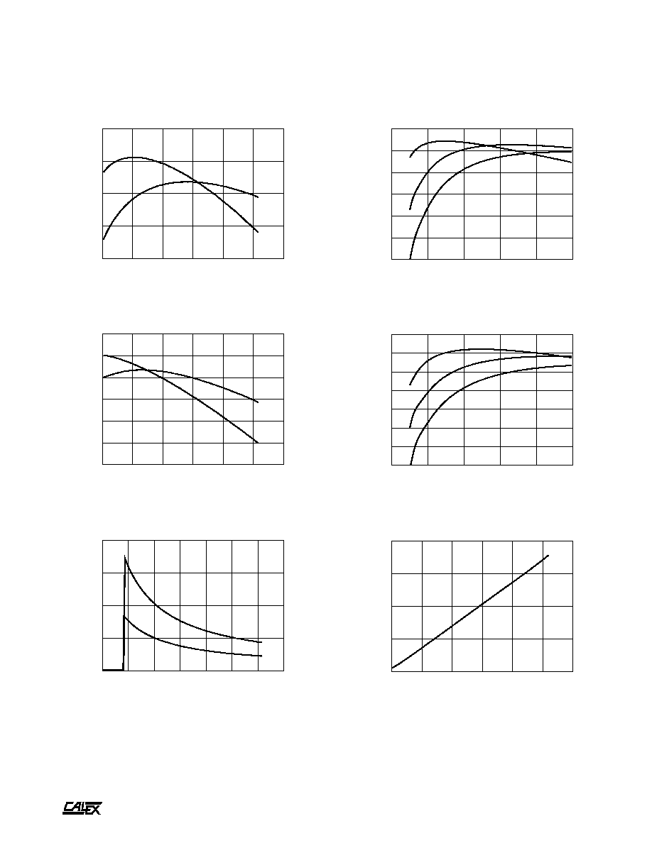
Typical Performance (Tc=25∞C, Full Rated Load).
5
10
15
20
25
30
35
40
LINE INPUT (VOLTS)
72
74
76
78
80
82
EFFICIENCY (%)
24S5.5000XW EFFICIENCY Vs. LINE INPUT
50% FULL LOAD
100% FULL LOAD
0
20
40
60
80
100
LOAD (%)
60
65
70
75
80
85
EFFICIENCY (%)
24S5.5000XW EFFICIENCY Vs. LOAD
LINE = 9VDC
LINE = 24VDC
LINE = 36VDC
5
10
15
20
25
30
35
40
LINE INPUT (VOLTS)
78
79
80
81
82
83
84
85
86
EFFICIENCY (%)
24S15.2000XW EFFICIENCY Vs. LINE INPUT
50% FULL LOAD
100% FULL LOAD
0
20
40
60
80
100
LOAD (%)
55
60
65
70
75
80
85
90
EFFICIENCY (%)
24S15.2000XW EFFICIENCY Vs. LOAD
LINE = 9VDC
LINE = 24VDC
LINE = 36VDC
0
10
20
30
40
LINE INPUT (VOLTS)
0.0
0.5
1.0
1.5
2.0
2.5
3.0
3.5
4.0
4.5
INPUT CURRENT (AMPS)
24S INPUT CURRENT Vs. LINE INPUT VOLTAGE
50% FULL LOAD
100% FULL LOAD
5
10
15
20
25
30
35
40
LINE INPUT (VOLTS)
1
2
3
4
5
6
CURRENT (mAMPS)
24S5.5000XW IDLE CURRENT Vs. LINE INPUT
A
25 to 30 Watt XW Single Series DC/DC Converters
Manufacturing Company, Inc. ∑ Concord, California 94520 ∑ Ph: 925/687-4411 or 800/542-3355 ∑ Fax: 925/687-3333 ∑ www.calex.com ∑ Email: sales@calex.com
5
eco# 041007-1
20
30
40
50
60
70
80
LINE INPUT (VOLTS)
76
78
80
82
84
EFFICIENCY (%)
48S5.5000XW EFFICIENCY Vs. LINE INPUT
50% FULL LOAD
100% FULL LOAD
20
30
40
50
60
70
80
LINE INPUT (VOLTS)
76
78
80
82
84
86
88
EFFICIENCY (%)
48S15.2000XW EFFICIENCY Vs. LINE INPUT
50% FULL LOAD
100% FULL LOAD
10
20
30
40
50
60
70
80
LINE INPUT (VOLTS)
0.0
0.5
1.0
1.5
2.0
INPUT CURRENT (AMPS)
48S INPUT CURRENT Vs. LINE INPUT VOLTAGE
50% FULL LOAD
100% FULL LOAD
Typical Performance (Tc=25∞C, Full Rated Load).
0
20
40
60
80
100
LOAD (%)
55
60
65
70
75
80
85
EFFICIENCY (%)
48S5.5000XW EFFICIENCY Vs. LOAD
LINE = 9VDC
LINE = 24VDC
LINE = 36VDC
0
20
40
60
80
100
LOAD (%)
55
60
65
70
75
80
85
90
EFFICIENCY (%)
48S15.2000XW EFFICIENCY Vs. LOAD
LINE = 9VDC
LINE = 24VDC
LINE = 36VDC
20
30
40
50
60
70
80
LINE INPUT (VOLTS)
2
4
6
8
10
CURRENT (mAMPS)
48S5.5000XW IDLE CURRENT Vs. LINE INPUT
A
25 to 30 Watt XW Single Series DC/DC Converters
Manufacturing Company, Inc. ∑ Concord, California 94520 ∑ Ph: 925/687-4411 or 800/542-3355 ∑ Fax: 925/687-3333 ∑ www.calex.com ∑ Email: sales@calex.com
6
eco# 041007-1
0
20
40
60
80
100
120
140
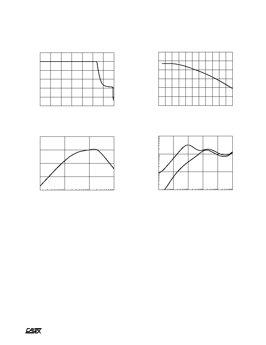
OUTPUT LOAD (%)
0
20
40
60
80
100
120
OUTPUT VOLTAGE (%)
OUTPUT VOLTAGE Vs. OUTPUT LOAD
Typical Performance (Tc=25∞C, Full Rated Load).
10
100
1000
10000
FREQUENCY (Hz)
-110
-100
-90
-80
-70
ATTENUATION (dB)
48S5.5000XW LINE TO OUTPUT TRANSFER FUNCTION
CURRENT
LIMIT
MODE
HICKUP
MODE
-30
-20
-10
0
10
20
30
40
50
60
70
80
CASE TEMPERATURE (Deg C)
-0.8
-0.6
-0.4
-0.2
0.0
0.2
0.4
NORMALIZED OUTPUT (%)
OUTPUT VOLTAGE Vs. CASE TEMPERATURE
FREQUENCY (Hz)
.001
.01
.1
1
IMPEDANCE (OHMS)
OUTPUT IMPEDANCE Vs. FREQUENCY
5V OUTPUT
15V OUTPUT
10
100
1K
10K
100K
1M