
A
6 Watt EC Single Series DC/DC Converters
Manufacturing Company, Inc. ∑ Concord, California 94520 ∑ Ph: 925/687-4411 or 800/542-3355 ∑ Fax: 925/687-3333 ∑ www.calex.com ∑ Email: sales@calex.com
1
eco# 041007-1
6 Watt EC Single Series Block Diagram
Description
These 6 Watt DC/DC converters were designed expressly for
fast integration with your systems power needs. With few
external components or filtering needed for all but the most
critical applications, these converters drop onto your board
and provide power instantly. This saves you costly engineering
time needed to design your system around the power converter,
"We've done the engineering for you".
Saving space in today's modern designs is also critical.
The EC Series converters replace narrow input voltage range
2 x 2 inch converters with a space saving 1 x 2 inch design.
This series has the highest isolation of any high power density
1 x 2 inch DC/DC converter on the market - we guarantee the
full UL1459 mandated value of 700 VDC.
Reliability is the most important design criteria for the
CALEX design team. To this end we reduced the component
count 50% from our last generation of 6 Watt devices and
reduced the case footprint.
CALEX reliability is backed by our 5 year warranty. We can
offer a 5 year warranty where others can't because with a
CALEX DC/DC it's rarely needed.
Features
Few External Parts Required for Operation
Efficiencies to 80 Percent
Overcurrent Protected for Long, Reliable Operation
Water Washable, Non-conductive Case Design
Low Input to Output Capacitance
Isolation Voltage Raised to 700 VDC as Per the
Requirements of UL1459
Five Year Warranty
t
r
a
h
C
n
o
i
t
c
e
l
e
S
l
e
d
o
M
e
g
n
a
R
t
u
p
n
I
C
D
V
t
u
p
t
u
O
C
D
V
t
u
p
t
u
O
A
m
n
i
M
x
a
M
C
E
0
0
0
1
.
5
S
2
1
9
7
2
5
0
0
0
1
C
E
0
0
5
.
2
1
S
2
1
9
7
2
2
1
0
0
5
C
E
0
0
4
.
5
1
S
2
1
9
7
2
5
1
0
0
4
C
E
0
0
0
1
.
5
S
8
4
0
2
0
6
5
0
0
0
1
C
E
0
0
5
.
2
1
S
8
4
0
2
0
6
2
1
0
0
5
C
E
0
0
4
.
5
1
S
8
4
0
2
0
6
5
1
0
0
4
1
2
3
4
CURRENT
MODE
PWM
ISOLATION TRANSFORMER
ISO AMP
LOW TC
BANDGAP
REFERENCE
+ OUTPUT
CMN
+ INPUT
- INPUT
A
6 Watt EC Single Series DC/DC Converters
Manufacturing Company, Inc. ∑ Concord, California 94520 ∑ Ph: 925/687-4411 or 800/542-3355 ∑ Fax: 925/687-3333 ∑ www.calex.com ∑ Email: sales@calex.com
2
eco# 041007-1
NOTES
*
All parameters measured at Tc=25∞C, nominal input voltage
and full rated load unless otherwise noted. Refer to the
CALEX Application Notes for the definition of terms,
measurement circuits and other information.
(1)
Noise is measured per CALEX Application Notes. Measurement
bandwidth is 0-20 MHz for peak-peak measurements, 10 kHz to
1 MHz for RMS measurements. Output noise is measured with
a 0.1µF / 50V ceramic capacitor in parallel with a 1µf / 35V
Tantalum capacitor, 1 inch from the output pins to simulate
standard PCB decoupling capacitance. Reflected Ripple is
measured with the appropriate input capacitor, and into a 10 µH
source impedance. See application notes for input capacitor
requirements.
(2)
To determine the correct fuse size, see CALEX Application
Notes.
(3)
Short term stability is specified after a 30 minute warmup at full
load, constant line and recording the drift over a 24 hour period.
(4)
The transient response is specified as the time required to settle
from a 50 to 75% step load change (rise time of step = 2 µs)
to a 1% error band.
(5)
Dynamic response is the peak overshoot during a transient
as defined in note 4 above.
(6)
The input ripple rejection is specified for DC to 120 Hz ripple with
a modulation amplitude of 1% of Vin.
(7)
The case thermal impedance is specified as the case temperature
rise over ambient per package watt dissipated.
(8)
Water Washability - Calex DC/DC converters are designed to
withstand most solder/wash processes. Careful attention should
be used when assessing the applicability in your specific
manufacturing process. Converters are not hermetically sealed.
*
s
r
e
t
e
m
a
r
a
P
t
u
p
n
I
l
e
d
o
M
C
E
0
0
0
1
.
5
S
2
1
C
E
0
0
5
.
2
1
S
2
1
C
E
0
0
4
.
5
1
S
2
1
C
E
0
0
0
1
.
5
S
8
4
C
E
0
0
5
.
2
1
S
8
4
C
E
0
0
4
.
5
1
S
8
4
s
t
i
n
U
e
g
n
a
R
e
g
a
t
l
o
V
N
I
M
X
A
M
9
7
2
0
2
0
6
C
D
V
)
1
(
e
l
p
p
i
R
d
e
t
c
e
l
f
e
R
r
o
t
i
c
a
p
a
C
l
a
n
r
e
t
x
E
h
t
i
W
P
Y
T
4
3
S
M
R
A
m
)
1
(
e
l
p
p
i
R
d
e
t
c
e
l
f
e
R
r
o
t
i
c
a
p
a
C
t
u
o
h
t
i
w
P
Y
T
P
Y
T
8
.
1
3
9
.
0
5
8
.
0
4
4
.
0
P
-
P
A
S
M
R
A
d
a
o
L
ll
u
F
t
n
e
r
r
u
C
t
u
p
n
I
d
a
o
L
o
N
P
Y
T
P
Y
T
7
0
5
6
0
0
6
2
1
0
3
1
5
4
5
1
6
A
m
y
c
n
e
i
c
i
f
f
E
P
Y
T
2
8
3
8
3
8
0
8
2
8
2
8
%
y
c
n
e
u
q
e
r
F
g
n
i
h
c
t
i
w
S
P
Y
T
5
2
1
z
H
k
e
g
a
t
l
o
v
r
e
v
O
t
u
p
n
I
m
u
m
i
x
a
M
m
u
m
i
x
a
M
s
m
0
0
1
s
l
e
d
o
m
S
2
1
s
l
e
d
o
M
S
8
4
X
A
M
4
3
2
7
C
D
V
,
e
m
i
T
n
o
-
n
r
u
T
r
o
r
r
E
t
u
p
t
u
O
%
1
P
Y
T
6
s
m
e
s
u
F
d
e
d
n
e
m
m
o
c
e
R
)
2
(
S
P
M
A
*
s
r
e
t
e
m
a
r
a
P
t
u
p
t
u
O
l
e
d
o
M
C
E
0
0
0
1
.
5
S
2
1
C
E
0
0
0
1
.
5
S
8
4
C
E
0
0
5
.
2
1
S
2
1
C
E
0
0
5
.
2
1
S
8
4
C
E
0
0
4
.
5
1
S
2
1
C
E
0
0
4
.
5
1
S
8
4
s
t
i
n
U
e
g
a
t
l
o
V
t
u
p
t
u
O
5
2
1
5
1
C
D
V
y
c
a
r
u
c
c
A
e
g
a
t
l
o
V
t
u
p
t
u
O
N
I
M
P
Y
T
X
A
M
5
9
.
4
0
0
.
5
5
0
.
5
0
9
.
1
1
0
0
.
2
1
0
1
.
2
1
0
9
.
4
1
0
0
.
5
1
0
1
.
5
1
C
D
V
e
g
n
a
R
d
a
o
L
d
e
t
a
R
N
I
M
X
A
M
0
.
0
0
.
1
0
.
0
5
.
0
0
.
0
4
.
0
A
n
o
i
t
a
l
u
g
e
R
d
a
o
L
f
o
%
0
0
1
-
%
5
2
d
a
o
L
d
e
t
a
R
P
Y
T
X
A
M
1
.
0
3
.
0
2
.
0
4
.
0
2
.
0
4
.
0
%
n
o
i
t
a
l
u
g
e
R
e
n
i
L
C
D
V
x
a
M
o
t
n
i
M
=
n
i
V
P
Y
T
X
A
M
2
0
.
0
2
.
0
2
.
0
8
.
0
2
.
0
8
.
0
%
)
3
(
y
t
il
i
b
a
t
S
m
r
e
T
t
r
o
h
S
P
Y
T
5
0
.
0
<
s
r
H
4
2
/
%
y
t
il
i
b
a
t
S
m
r
e
T
g
n
o
L
P
Y
T
1
.
0
<
s
r
H
k
/
%
)
4
(
e
s
n
o
p
s
e
R
t
n
e
i
s
n
a
r
T
P
Y
T
0
5
2
0
0
3
s
µ
)
5
(
e
s
n
o
p
s
e
R
c
i
m
a
n
y
D
P
Y
T
5
7
0
5
2
k
a
e
p
V
m
)
6
(
n
o
i
t
c
e
j
e
R
e
l
p
p
i
R
t
u
p
n
I
P
Y
T
0
4
>
B
d
)
1
(
k
a
e
P
-
k
a
e
P
,
e
s
i
o
N
P
Y
T
0
5
P
-
P
V
m
e
s
i
o
N
S
M
R
P
Y
T
8
S
M
R
V
m
t
n
e
i
c
i
f
f
e
o
C
e
r
u
t
a
r
e
p
m
e
T
P
Y
T
X
A
M
0
5
0
5
1
C
∞
/
m
p
p
o
t
n
o
i
t
c
e
t
o
r
P
t
i
u
c
r
i
C
t
r
o
h
S
s
t
u
p
t
u
O
ll
a
r
o
f
n
o
m
m
o
C
n
o
i
t
c
e
t
o
r
P
t
i
m
i
L
t
n
e
r
r
u
C
,
s
u
o
u
n
i
t
n
o
C

A
6 Watt EC Single Series DC/DC Converters
Manufacturing Company, Inc. ∑ Concord, California 94520 ∑ Ph: 925/687-4411 or 800/542-3355 ∑ Fax: 925/687-3333 ∑ www.calex.com ∑ Email: sales@calex.com
3
eco# 041007-1
n
i
P
n
o
i
t
c
n
u
F
1
T
U
P
N
I
+
2
T
U
P
N
I
-
3
T
U
P
T
U
O
+
4
N
M
C
Mechanical tolerances unless otherwise noted:
X.XX dimensions: ±0.040 inches
X.XXX dimensions: ±0.010 inches
Application Information
General Information
The 125 kHz operating frequency of the 6 Watt EC Single
series allows an increased power density over the last
generation of 2 X 2 inch converters.
The series is also mindful of battery operation for industrial,
medical control and remote data collection applications. The
no-load input current draws typically less than 7 mA from the
input source.
Full overload protection is provided by independent pulse-
by-pulse current limiting. These protection features assure
you that our 6 Watt single will provide you with zero failure rate
operation.
A fully sealed, water washable, non-conductive case is
standard along with specified operation over the full commercial
temperature range of -40 to +100 ∞C.
General Operation
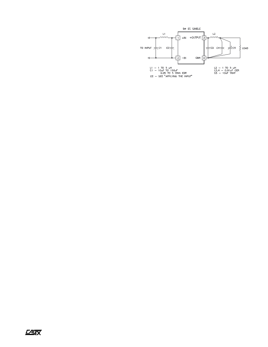
Figure 1 shows the recommended connections for the 6 Watt
EC Single DC/DC converter. A fuse is recommended to
protect the input circuit and should not be omitted. The fuse
prevents unlimited current from flowing in the case of a
catastrophic system failure.
No external capacitance on the output is required for
normal operation, in fact it can degrade the converters
performance. See our application note "Understanding DC/
DC Converters Output Impedance" and the low noise circuits
later in this data sheet for more information. The usual 10 µF
and 0.1 to 0.001 µF bypasses may be used around your PCB
as required for local bypassing without harm.
Figure 1.
Standard connections for the 6 Watt EC Single. The input fuse
should not be omitted. The overvoltage diodes D1 and D2 may be
added to the circuit directly at the converter to provide transient
protection to your circuit. In some circuits capacitor C1 may be
required, see the section "Applying The Input" for more information.
Applying the Input
The input to the 6 Watt EC single series should be buffered
with a high ripple current capacitor (C1 in Figure 1) if it is an
appreciable distance from your input source. A capacitor
capable of handling the input ripple current of the EC series
should be used (see the input reflected ripple current curves
for exact values). Use the minimum size required for your
output power level and minimum input voltage to keep your
system small and cost effective.
Applicable capacitor types for worst case applications are
detailed below. Worst case is defined as continuous operation
at full load, minimum line and high ambient temperatures. The
capacitor that you will need will probably be smaller if one or
all of the worst case conditions listed is relaxed.
BOTTOM VIEW
SIDE VIEW
*
s
n
o
i
t
a
c
i
f
i
c
e
p
S
l
a
r
e
n
e
G
s
l
e
d
o
M
l
l
A
s
t
i
n
U
n
o
i
t
a
l
o
s
I
e
g
a
t
l
o
V
n
o
i
t
a
l
o
s
I
t
u
p
t
u
O
o
t
t
u
p
n
I
e
g
a
k
a
e
L
A
µ
0
1
N
I
M
0
0
7
C
D
V
t
u
p
t
u
O
o
t
t
u
p
n
I
e
c
n
a
t
i
c
a
p
a
C
P
Y
T
0
0
4
F
p
l
a
t
n
e
m
n
o
r
i
v
n
E
e
g
n
a
R
g
n
i
t
a
r
e
p
O
e
s
a
C
g
n
i
t
a
r
e
D
o
N
N
I
M
X
A
M
0
4
-
0
0
1
C
∞
e
g
n
a
R
e
g
a
r
o
t
S
N
I
M
X
A
M
5
5
-
5
0
1
C
∞
)
7
(
e
c
n
a
d
e
p
m
I
l
a
m
r
e
h
T
P
Y
T
0
2
t
t
a
W
/
C
∞
l
a
r
e
n
e
G
t
h
g
i
e
W
t
i
n
U
P
Y
T
1
z
o
s
t
i
K
g
n
i
t
n
u
o
M
s
i
s
s
a
h
C
5
1
S
M
,
8
S
M
,
6
S
M
s
l
a
v
o
r
p
p
A
y
c
n
e
g
A
0
5
9
0
6
L
U
/
A
S
C
A
6 Watt EC Single Series DC/DC Converters
Manufacturing Company, Inc. ∑ Concord, California 94520 ∑ Ph: 925/687-4411 or 800/542-3355 ∑ Fax: 925/687-3333 ∑ www.calex.com ∑ Email: sales@calex.com
4
eco# 041007-1
Suggested Capacitors
12 Volt Inputs
Panasonic
HFQ Series
Suggested Part:
ECA1HFQ271
270µF, 50V, 105∞C Rated
10 x 25 mm
ESR=0.090 Ohms
Allowable Ripple=1.040 A @ 105∞C
Nichicon
PF or PL Series
Suggested Part:
UPL1H221MPH6
220µF, 50V, 105∞C Rated
10 x 25 mm
ESR=0.075 Ohms
Allowable Ripple=1.040 A @ 105∞C
United Chemi-Con LXF, KMF, or SXE Series
Suggested Part:
LXF50VB221M10X25LL
220µF, 50V, 105∞C Rated
10 x 25 mm
ESR=0.063 Ohms
Allowable Ripple=1.150 A @ 105∞C
48 Volt Inputs
Panasonic
HFE Series
Suggested Part:
ECEA2AFE680,
68µF, 100V, 105∞C Rated
12.5 x 15 mm
ESR=0.28 Ohms
Allowable Ripple=0.511 A @ 105∞C
Nichicon
PR Series
Suggested Part:
UPR2A101MRH
100µF, 100V, 105∞C Rated
12.5 x 20 mm
Allowable Ripple=0.577 A @ 105∞C
United Chemi-Con KMF, SXE
Suggested Part:
KMF100VB470M10X16LL
47µF, 100V, 105∞C Rated
10 x 16 mm
ESR=0.32 Ohms
Allowable Ripple=0.500 A @ 105∞C
Applying the Output
The output is simply connected to your application circuit and
away you go. If extra low output noise is required in your
application the circuit shown in Figure 2 may be used to
reduce the output noise to below 10 mV peak-peak.
Grounding
The input and output sections are fully floating from each
other. They may be operated fully floating or with a common
ground. If the input and output sections are connected either
directly at the converter or at some remote location from the
Figure 2.
For very low noise applications the circuits shown above can be
used. The input current ripple will be reduced approximately 30 dB
of the original value while the output noise will be reduced to below
10 mV p-p. Do not use the biggest lowest ESR capacitors that you
can find in these circuits. These types of capacitors will cause
severe peaking in the filters transfer function and may actually make
the conducted noise worse.
converter it is suggested that a 1 to 10µF, 0.5 to 5 Ohm ESR
capacitor bypass be used directly at the converter output pins.
This capacitor prevents any common mode switching currents
from showing up at the converters output as normal mode
output noise. Do not use the lowest ESR, biggest value
capacitor that you can find! This can only lead to reduced
system performance or oscillation. See our application note
"Understanding Output Impedance For Optimum Decoupling"
for more information.
Temperature Derating
The EC Single series can operate up to 100∞C case
temperature without derating. Case temperature may be
roughly calculated from ambient by knowing that the 6 Watt
EC Singles case temperature rise is approximately 20∞C per
package watt dissipated.
For example: If a 48 volt input converter was delivering 4
Watts, at 48 volts input at what ambient could it expect to run
with no moving air and no extra heatsinking?
Efficiency for a EC Single is approximately 78%. A little less
for some - a little more for others, check the product curves for
exact information. This leads to an input power of about 5
Watts. Therefore the case dissipation is 5 Watts (input power)
minus 4 Watts (output power) or 1 Watt. The case temperature
rise would be 1 Watt x 20∞C/W = 20∞C. This number is
subtracted from the maximum case temperature of 100∞C to
get: 80∞C.
This is a rough approximation to the maximum ambient
temperature. Because of the difficulty of defining ambient
temperature and the possibility that the loads dissipation may
actually increase the local ambient temperature significantly
or that convection cooling is suppressed by physical placement
of the module, these calculations should be verified by actual
measurement of operating temperature and your circuits
exact efficiency (efficiency depends on both line input and
load value) before committing to a production design.
A
6 Watt EC Single Series DC/DC Converters
Manufacturing Company, Inc. ∑ Concord, California 94520 ∑ Ph: 925/687-4411 or 800/542-3355 ∑ Fax: 925/687-3333 ∑ www.calex.com ∑ Email: sales@calex.com
5
eco# 041007-1
.
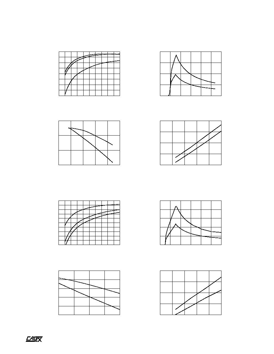
Typical Performance (Tc=25∞C, Vin=Nom VDC, Rated Load).
Data for 12 Volt Input Models
0
10
20
30
40
50
60
70
80
90
100
LOAD(%)
45
50
55
60
65
70
75
80
85
EFFICIENCY(%)
12 VOLT EFFICIENCY Vs. LOAD
LINE = 9VDC
LINE = 12VDC
LINE = 27VDC
0
5
10
15
20
25
30
LINE INPUT(VOLTS)
0.00
0.25
0.50
0.75
1.00
INPUT CURRENT(AMPS)
12 VOLT INPUT CURRENT Vs. LINE INPUT VOLTAGE
100% LOAD
50% LOAD
5
10
15
20
25
30
LINE INPUT(VOLTS)
70
75
80
85
EFFICIENCY(%)
12 VOLT EFFICIENCY Vs. LINE INPUT VOLTAGE
100% LOAD
50% LOAD
0
20
40
60
80
100
LOAD (%)
0.20
0.40
0.60
0.80
1.00
CAPACITOR CURRENT (AMPS RMS)
12 VOLT CAPACITOR CURRENT Vs. LOAD
5V OUTPUT
12V & 15V OUTPUT
Data for 48 Volt Input Models
20
30
40
50
60
LINE INPUT(VOLTS)
65
70
75
80
85
90
EFFICIENCY(%)
48 VOLT EFFICIENCY Vs. LINE INPUT VOLTAGE
100% LOAD
50% LOAD
0
20
40
60
80
100
LOAD (%)
0.10
0.20
0.30
0.40
0.50
CAPACITOR CURRENT (AMPS RMS)
48 VOLT CAPACITOR CURRENT Vs. LOAD
5V OUTPUT
12V & 15V OUTPUT
0
10
20
30
40
50
60
70
80
90
100
LOAD(%)
40
45
50
55
60
65
70
75
80
85
90
EFFICIENCY(%)
48 VOLT EFFICIENCY Vs. LOAD
LINE = 20VDC
LINE = 48VDC
LINE = 60VDC
0
10
20
30
40
50
60
LINE INPUT(VOLTS)
0.0
0.1
0.2
0.3
0.4
0.5
INPUT CURRENT(AMPS)
48 VOLT INPUT CURRENT Vs. LINE INPUT VOLTAGE
100% LOAD
50% LOAD

A
6 Watt EC Single Series DC/DC Converters
Manufacturing Company, Inc. ∑ Concord, California 94520 ∑ Ph: 925/687-4411 or 800/542-3355 ∑ Fax: 925/687-3333 ∑ www.calex.com ∑ Email: sales@calex.com
6
eco# 041007-1
Typical Performance (Tc=25∞C, Vin=Nom VDC, Rated Load).
Data for All Models
0
20
40
60
80
100
120
140
160
180
200
OUTPUT LOAD (%)
0
20
40
60
80
100
120
NORMALIZED OUTPUT (%)
OUTPUT VOLTAGE Vs. OUTPUT LOAD
CURRENT LIMIT MODE ->
"HICKUP" MODE ->
-40
-20
0
20
40
60
80
100
120
AMBIENT TEMPERATURE (Deg C)
0
20
40
60
80
100
120
OUTPUT POWER (%)
DERATING
INFINITE HEAT SINK
NO HEAT SINK
SAFE OPERATING AREA
-40
-20
0
20
40
60
80
100
CASE TEMPERATURE (Deg C)
-0.4
-0.3
-0.2
-0.1
0.0
0.1
0.2
NORMALIZED OUTPUT (%)
OUTPUT VOLTAGE Vs. CASE TEMPERATURE
10
100
1000
10000
100000
1000000
FREQUENCY (Hz)
.0001
.001
.01
.1
1
10
OUTPUT IMPEDANCE (OHMS)
OUTPUT IMPEDANCE Vs. FREQUENCY
5 VOLT
12 AND 15 VOLT