 | –≠–ª–µ–∫—Ç—Ä–æ–Ω–Ω—ã–π –∫–æ–º–ø–æ–Ω–µ–Ω—Ç: 6202-2965 | –°–∫–∞—á–∞—Ç—å:  PDF PDF  ZIP ZIP |

A
Models 940 and 945 DC Transmitters
Manufacturing Company, Inc. ∑ Concord, California 94520 ∑ Ph: 925/687-4411 or 800/542-3355 ∑ Fax: 925/687-3333 ∑ www.calex.com ∑ Email: sales@calex.com
1
Features
!
4 to 20mA Output
!
0 to +10V Input - Model 940
!
0 to 50 mV Input - Model 945
!
700 Volts DC Isolation
!
PC Board Mount Modular Design for
OEM Applications
!
Convenient Mounting Kit Available for
End User Applications
!
Powered by 14 to 16 Volts
!
24 VDC Operation Available
Description
The CALEX Model 940 and 945 are fully DC isolated voltage
to current transmitters. They are ideal for eliminating ground
loops and common mode problems in data acquisition and
process control systems. The 20 Volt maximum output
compliance voltage allows a loop resistance of up to 1000
ohms. The isolation input to output is 700 Volts DC. The input
and output are also isolated from the unregulated +14 to +16
VDC power source.
Model 940 and 945 Block Diagram

A
Models 940 and 945 DC Transmitters
Manufacturing Company, Inc. ∑ Concord, California 94520 ∑ Ph: 925/687-4411 or 800/542-3355 ∑ Fax: 925/687-3333 ∑ www.calex.com ∑ Email: sales@calex.com
2
s
t
n
e
m
n
g
i
s
s
A
n
i
P
1
T
U
P
N
I
+
2
T
U
P
N
I
-
3
N
R
U
T
E
R
4
N
R
U
T
E
R
5
T
U
P
T
U
O
T
N
E
R
R
U
C
6
m
a
r
g
a
i
D
k
c
o
l
B
5
4
9
/
0
4
9
l
e
d
o
M
e
c
n
e
r
e
f
e
R
7
m
a
r
g
a
i
D
k
c
o
l
B
5
4
9
/
0
4
9
l
e
d
o
M
e
c
n
e
r
e
f
e
R
8
m
a
r
g
a
i
D
k
c
o
l
B
5
4
9
/
0
4
9
l
e
d
o
M
e
c
n
e
r
e
f
e
R
9
R
E
W
O
P
C
D
-
0
1
R
E
W
O
P
C
D
+
t
u
p
n
I
0
4
9
5
4
9
e
g
a
t
l
o
V
s
t
l
o
V
0
1
+
o
t
0
V
m
0
5
o
t
0
e
c
n
a
t
s
i
s
e
R
m
u
m
i
n
i
m
m
h
o
g
e
m
0
1
t
u
p
t
u
O
t
n
e
r
r
u
C
A
m
0
2
o
t
4
e
c
n
a
t
s
i
s
e
R
d
a
o
L
m
h
o
0
0
0
1
o
t
0
e
c
n
a
il
p
m
o
C
m
u
m
i
x
a
m
s
t
l
o
V
0
2
e
s
n
o
p
s
e
R
y
c
n
e
u
q
e
r
F
B
d
3
@
z
H
0
0
4
e
m
i
T
e
s
i
R
s
m
9
.
0
%
1
.
0
o
t
e
m
i
T
g
n
il
t
t
e
S
s
m
5
.
2
e
s
i
o
N
w
b
z
H
k
1
w
b
z
H
M
0
2
P
-
P
A
µ
1
P
-
P
A
µ
0
5
y
t
i
v
i
t
i
s
n
e
S
y
l
p
p
u
S
r
e
w
o
P
o
r
e
Z
n
a
p
S
t
l
o
V
/
A
µ
5
t
l
o
V
/
%
5
0
0
.
0
5
2
@
y
c
a
r
u
c
c
A
∞C
e
l
a
c
S
ll
u
F
f
o
%
1
.
0
y
t
i
r
a
e
n
i
L
e
l
a
c
S
ll
u
F
f
o
%
5
0
.
0
t
n
e
i
c
i
f
f
e
o
C
e
r
u
t
a
r
e
p
m
e
T
C
∞
5
5
o
t
0
o
r
e
Z
n
a
p
S
e
l
a
c
S
ll
u
F
f
o
C
∞
/
%
5
3
0
0
.
0
e
l
a
c
S
ll
u
F
f
o
C
∞
/
%
5
3
0
0
.
0
t
u
p
t
u
O
o
t
t
u
p
n
I
-
n
o
i
t
a
l
o
s
I
y
l
p
p
u
S
r
e
w
o
P
r
o
C
D
s
t
l
o
V
0
0
7
e
c
n
a
t
i
c
a
p
a
C
F
p
5
2
s
t
n
e
m
e
r
i
u
q
e
R
r
e
w
o
P
e
g
a
t
l
o
V
C
D
C
D
s
t
l
o
V
6
1
o
t
4
1
t
n
e
r
r
u
C
A
m
5
2
1
t
e
S
o
r
e
Z
.
t
n
e
r
r
u
c
o
r
e
Z
A
m
4
t
e
s
o
t
d
e
r
i
u
q
e
R
r
e
t
e
m
o
i
t
n
e
t
o
P
t
e
m
r
e
C
l
a
n
r
e
t
x
E
.
A
m
0
2
o
t
0
t
n
e
r
r
u
c
t
u
p
t
u
o
t
e
s
o
t
d
e
s
u
e
b
y
a
m
t
o
P
l
a
n
r
e
t
x
E
t
n
e
m
n
o
r
i
v
n
E
e
g
a
k
c
a
P
e
l
u
d
o
M
c
i
t
s
a
l
P
d
e
t
a
l
u
s
p
a
c
n
E
)
s
e
h
c
n
i
(
e
z
i
S
"
6
.
0
x
"
2
x
"
2
t
h
g
i
e
W
.
z
o
5
.
2
Specifications
Operation
For 4 to 20 mA operation, a 200 ohm external cermet
potentiometer is required to set 4 mA Zero Current. Connect
the wiper to pins 6 and 8. Connect one end terminal to pin 7
with a 604 ohm 1% resistor in series. Connect the other end
terminal to pin 8. Tie pin 4 to pin 3. Reference Model 940 Block
Diagram.
Mechanical Specifications
BOTTOM VIEW

A
Models 940 and 945 DC Transmitters
Manufacturing Company, Inc. ∑ Concord, California 94520 ∑ Ph: 925/687-4411 or 800/542-3355 ∑ Fax: 925/687-3333 ∑ www.calex.com ∑ Email: sales@calex.com
3
Mounting Kit
The MK940 mounting kit is an optional printed circuit board
that provides the necessary potentiometers and a connector
for a complete turnkey system.
The 940/MK940, when ordered as a combination, is shipped
from the factory configured as a 0 to +10 Volt input, 4 to 20mA
output, isolated transmitter. The 945/MK940, when ordered
as a combination, is shipped from the factory configured as a
0 to 50 mV input, 4 to 20 mA output, isolated transmitter. Note
in the schematic, Figure 1, that C1, R1, R2, R3, and R5 are
included on the board. The other designated components are
user supplied for other applications. Also note that R8 through
R11 are not connected to the rest of the circuit. For 24 VDC
operation, add a "-24" to the MK940, i.e. 945/MK940-24
Figure 2 shows the outline of the MK940 card and the lettered
pin assignments. The card includes a Model 015 connector
with edge guides and has eyelets for soldering wires. The
components described as jumpers are wire connections
although they have a ceramic body the size of a ºW resistor.
FIGURE 2. MK940 Card
FIGURE 1. MK940 Schematic
NOTE:
C1, R1, R2, R3, R5 ARE INCLUDED.
ALL OTHER COMPONENTS ARE USER
SUPPLIED FOR SPECIFIC APPLICATIONS.
Model 940/945
A
Models 940 and 945 DC Transmitters
Manufacturing Company, Inc. ∑ Concord, California 94520 ∑ Ph: 925/687-4411 or 800/542-3355 ∑ Fax: 925/687-3333 ∑ www.calex.com ∑ Email: sales@calex.com
4
MK940 Application
Isolated 0 to 20mA Output
NOTE:
R6 IS A 1% METAL FILM 1/4 W
RESISTOR.
ZERO CURRENT MAY BE 100µA
refer to locations labeled on the MK940. All fixed value
resistors should be metal film 1% type. Where a potentiometer
is shown, use a multiturn trim pot with a CERMET resistance
element. The hole pattern is for industry standard
potentiometers such as Bourns "3006Y", Spectrol "43", and
Beckman "89" series.
Applications
The 940/MK940 may be configured for 4 to 20mA output, as
a constant current source, as a 0 to 1mA current source, 0 to
5V output, voltage input and 1 to 5V output, or an isolated
voltage input and 4 to 20V output with a single pole 10Hz input
filter. Figures 3 through 8 illustrate these configurations with
the Model 940/945 and MK940 mounting kit. The R-numbers
MK940 Application
Isolated Constant Current Source
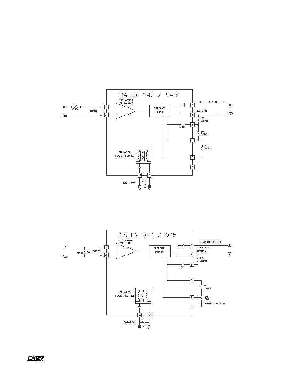
FIGURE 3.
Shows an isolated 0 to 20mA current loop. In this application the ZERO pot is not used and is replaced by a wire jumper. R6 parallels an internal
50 ohm resistor to change the scale factor. The zero current may be from 10nA to 100µA. Zero current must be checked with a short between
pins F and H, or 0 Volts input. Do not leave the input open.
FIGURE 4.
Is a potentiometer adjust 0 to 20mA constant current source which is isolated from the power supply. The jumper in place of R4 ensures that
the input is zero volts. Do not apply any control voltage to the input. The output will drive zero to 1000 ohms with a 15 volt power supply.
A
Models 940 and 945 DC Transmitters
Manufacturing Company, Inc. ∑ Concord, California 94520 ∑ Ph: 925/687-4411 or 800/542-3355 ∑ Fax: 925/687-3333 ∑ www.calex.com ∑ Email: sales@calex.com
5
NOTE:
R5 IS A 1% METAL FILM 1/4 W
RESISTOR.
NOTE:
R6 IS A 1% METAL FILM 1/4 W
RESISTOR.
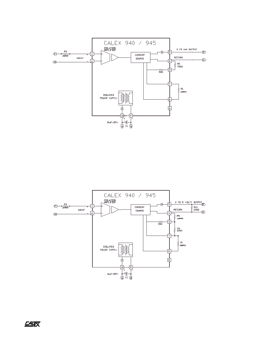
FIGURE 5.
Zero to 1mA current source. The load resistance may be 0 to 20,000 ohms. Other values of full scale current may be set by changing R5. The
maximum output current is determined by 0.8V/(R5+50) and is limited to 20 mA.
FIGURE 6.
Shows a voltage to voltage transmitter. Note that this configuration will have a 249 ohm output source resistance which will produce an error
of 2.5% if driving a 10,000 ohm load or 0.25% if driving a 100,000 ohm load. R6 parallels the internal 50 ohms to produce 20mA output with full
scale input. There will be 0.8 Volts between pins 7 and 4 with full scale input.
MK940 Application
Isolated 0 to 1mA Current Source
MK940 Application
Isolated 0 to 5 Volts Out