
©
2006 California Micro Devices Corp. All rights reserved.
06/30/06
490 N. McCarthy Blvd., Milpitas, CA 95035-5112
l
Tel: 408.263.3214
l
Fax: 408.263.7846
l
www.cmd.com
1
CM9100
PRELIMINARY
Features
∑
Monolithic linear charger requires no inductors,
external sense resistors or blocking diodes.
∑
A few external components are required
∑
4.75V to 6.5V operating input voltage range.
∑
Programmable the charging current to achieve the
fastest charging rate without the risk of overloading
the adapter
∑
Thermal limit control of charging current prevents
overheating
∑
Maximum of 1µA battery drain current
∑
Charging-current monitor output for system super-
vision of charging status
∑
TQFN-16, RoHS compliant lead-free package
Applications
∑
Cellular phones and smart phones
∑
PDAs Portable Media Viewers
∑
Digital Still Camera
∑
Cradle Chargers
Product Description
The CM9100 is an integrated linear-mode charger for
single-cell, Lithium-ion batteries. It designed for com-
pact and cost-sensitive handheld devices. It provides
programming charge current, charge status indicator,
high accuracy fast charge current and automatic
charge voltage regulation. It requires no external block-
ing diodes or current sense resistors and needs only
one external resistor to program the charging current.
The CM9100 provides Precharge, Fast-charge (con-
stant-current), and Termination (constant-voltage)
charging modes. The Precharge/Termination currents
are preset to 10/5% of the Fast-charge current level. A
host system can monitor the actual charge current at
the ISET pin.
When the chip temperature reach 140∞C, the CM9100
goes into a latched shutdown mode stop charging until
the chip temperature is below 140∞C will gradually
charge and 105∞C resume fast charge. When the
adapter is not present, the CM9100 draws less than
1µA of drain current from the battery in ultra low power
sleep mode.
The CM9100 is packaged in a miniature 16-pin TQFN.
It can operate over the ambient temperature range of
-40∞C to 85∞C.
Typical Application
Li-ion
Battery
GND
VOUT
VIN
Vin
4.7u
5k
ISET
STAT
CM9100
VREF
0.1u
1k
VSTB
1u
4.7u
Basic Compact Cost-effective Fast-Charger
©
2006 California Micro Devices Corp. All rights reserved.
2
490 N. McCarthy Blvd., Milpitas, CA 95035-5112
l
Tel: 408.263.3214
l
Fax: 408.263.7846
l
www.cmd.com
06/30/06
CM9100
PRELIMINARY
PIN DESCRIPTIONS
LEAD(s)
NAME
DESCRIPTION
1
NC
No connect.
2
GND
Ground pin.
3
NC
No connect.
4
VREF
4.2V, 2mA reference output pin.
5
ISET
Pin to set the maximum charging current in the Fast charge (CC) mode. Also,
reflects actual charging current. A resistor between this pin and ground sets the
charge current, I
CH
:
6
NC
No connect.
7
NC
No connect.
8
NC
No connect.
9
STAT
Charging status indicator pin (open-drain output).
10
NC
No connect.
11
VOUT
Charger output pin
12
NC
No connect.
13
VSTB
4.2V output pin, connect a cap to ground to increase stability.
14
NC
No connect.
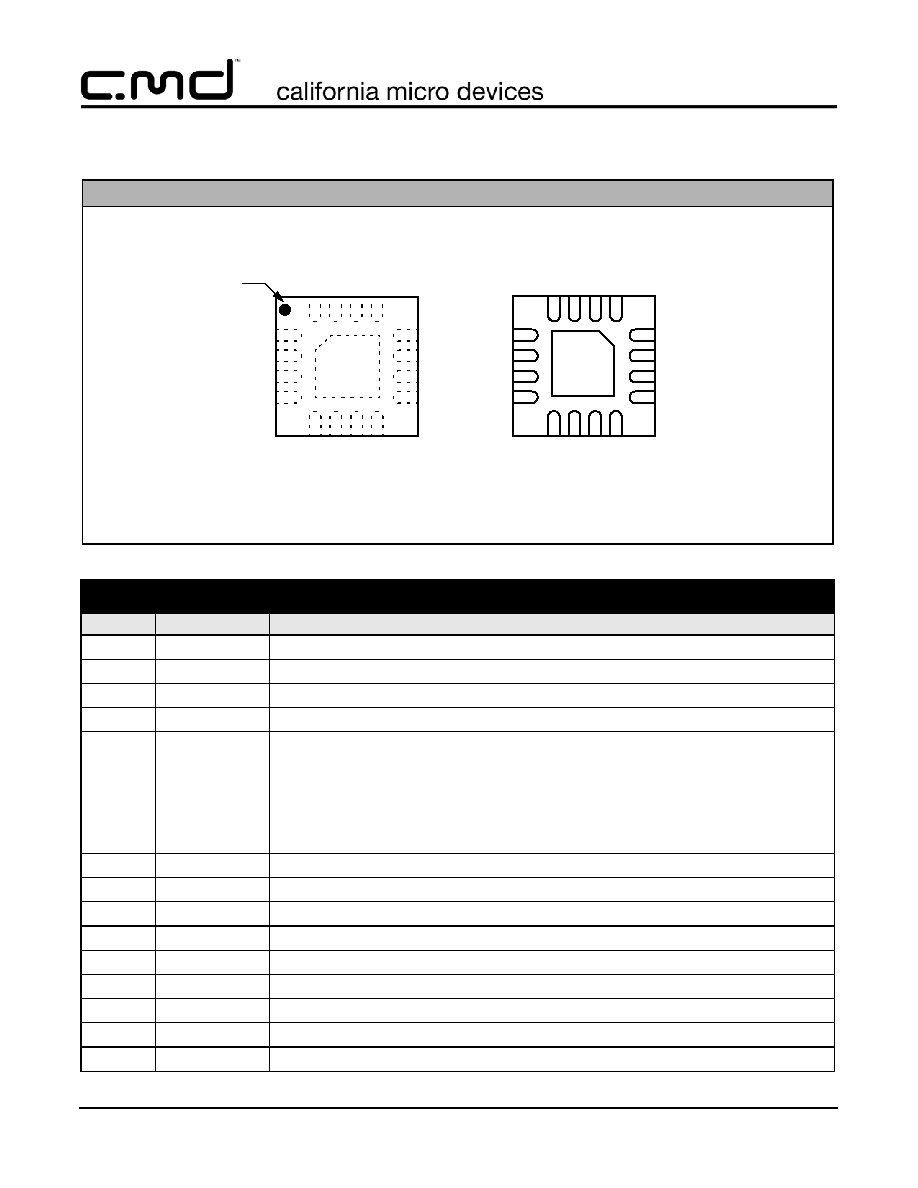
PACKAGE / PINOUT DIAGRAM
CM9100-00QE
4
3
2
1
9
10
11
12
5
6
7
8
16
15
14
13
GND
PAD
BOTTOM VIEW
(Pins Up View)
TOP VIEW
(Pins Down View)
VREF
NC
GND
NC
STAT
NC
VOUT
NC
VI
N
NC
NC
VS
TB
ISE
T
NC
NC
NC
4
3
2
1
9
10
11
12
5
6
7
8
16
15
14
13
CM91
0
000QE
Pin 1
Marking
16-Lead TQFN Package (4mm x 4mm)
Note: This drawing is not to scale.
R
ISET
1000 2.5
◊
V
I
CC
------------------------------
=
Package Pinout

©
2006 California Micro Devices Corp. All rights reserved.
06/30/06
490 N. McCarthy Blvd., Milpitas, CA 95035-5112
l
Tel: 408.263.3214
l
Fax: 408.263.7846
l
www.cmd.com
3
CM9100
PRELIMINARY
Ordering Information
Note 1: Parts are shipped in Tape & Reel form unless otherwise specified.
Specifications
15
NC
No connect.
16
VIN
Positive input supply voltage pin, which powers the charger.
PIN DESCRIPTIONS
PART NUMBERING INFORMATION
Pins
Package
Lead Free Finish
Ordering Part Number
1
Part Marking
16
TQFN
CM9100-00QE
CM910 000QE
ABSOLUTE MAXIMUM RATINGS
PARAMETER
RATING
UNITS
ESD Protection (HBM)
±2
kV
V
IN
to GND
[GND - 0.3] to +6.5
V
Pin Voltages
V
OUT
, V
REF
, V
STB
to GND
I
SET,
STAT
to GND
[GND - 0.3] to +6.5
[GND - 0.3] to +6.5
V
V
Storage Temperature Range
-65 to +150
∞C
Operating Temperature Range (Ambient)
-40 to +85
∞C
Lead Temperature (Soldering, 10sec)
300
∞C
ELECTRICAL OPERATING CHARACTERISTICS
(SEE NOTE 1)
SYMBOL
PARAMETER
CONDITIONS
MIN
TYP
MAX
UNITS
V
IN
VIN Supply Voltage
V
IN
4.75
6.5
V
I
Q
Quiescent Current
Charging modes, exclud-
ing current to ISET and
STAT pins. All outputs are
at no load.
2
mA
V
SHDN
Battery Drain Current
V
IN
= 0V (100
- resistor
to ground), V
BAT
= 4.2V
0.5
1
µA
Charger Function
I
PR
Precharge Mode Current
V
OUT
< 3.2V
0.85 x I
PR
1.14 x I
PR
mA
T
CC
CC Mode Voltage Threshold
3.20
3.30
3.40
V
I
PR
250
R
SET k
(
)
------------------------
=
Pin Descriptions (cont'd)
©
2006 California Micro Devices Corp. All rights reserved.
4
490 N. McCarthy Blvd., Milpitas, CA 95035-5112
l
Tel: 408.263.3214
l
Fax: 408.263.7846
l
www.cmd.com
06/30/06
CM9100
PRELIMINARY
Note 1: V
IN
= 5.0V. All outputs are on. T
A
= 25∞C unless otherwise specified.
Note 2: When chip temperature reaches 105∞C, the IC's internal thermal limit will maintain this temperature by decreasing the pro-
grammed charge current
Note 3: When chip temperature reaches 140∞C, the IC goes into a latched shutdown mode. It stops charging, stops supplying
V
OUT
). To resume the charging function, a toggle of V
IN
is required.
Note 4: When charging current reaches 1.2A, the IC goes into shutdown, latched mode only toggled V
IN
could resume the function.
I
CC
CC Mode Charging Current V
OUT
> 3.5V
0.92 x I
CC
1.08 x
I
CC
mA
V
CC
CV Mode Voltage Threshold
4.190
4.200
4.210
V
I
TERM
Charge Termination Current V
OUT
> 4.190V
0.8 x
I
TERM
1.2 x
I
TERM
mA
V
RCH
Recharge Mode Threshold
4.090
4.100
4.110
V
Constant-temperature
Mode, Limit
(Note 2)
95
105
125
C
OTP
Over-temperature Protec-
tion, Limit
(Note 3)
130
140
150
C
OCP
Over-Current Charging
(OCP), Limit
(Note 4)
0.9
1.0
1.1
A
R
DSON
of Charger MOSFET I
CC
= 500mA
100
120
150
m
VREF
V
REF
Regulated Voltage V
REF
I
REF
< 1mA
4.190
4.200
4.210
V
VSTB
V
STB
Regulated Voltage V
STB
4.100
4.200
4.300
V
Control Function
STAT
STAT (Open Drain) Output
Low Voltage
I
SINK
= 5mA
I
SINK
= 20mA
0.1
0.5
V
V
ELECTRICAL OPERATING CHARACTERISTICS
(SEE NOTE 1)
SYMBOL
PARAMETER
CONDITIONS
MIN
TYP
MAX
UNITS
I
CC
2500
R
SET k
(
)
------------------------
=
I
TERM
100
R
SET k
(
)
------------------------
=
Specifications (cont'd)
©
2006 California Micro Devices Corp. All rights reserved.
06/30/06
490 N. McCarthy Blvd., Milpitas, CA 95035-5112
l
Tel: 408.263.3214
l
Fax: 408.263.7846
l
www.cmd.com
5
CM9100
PRELIMINARY
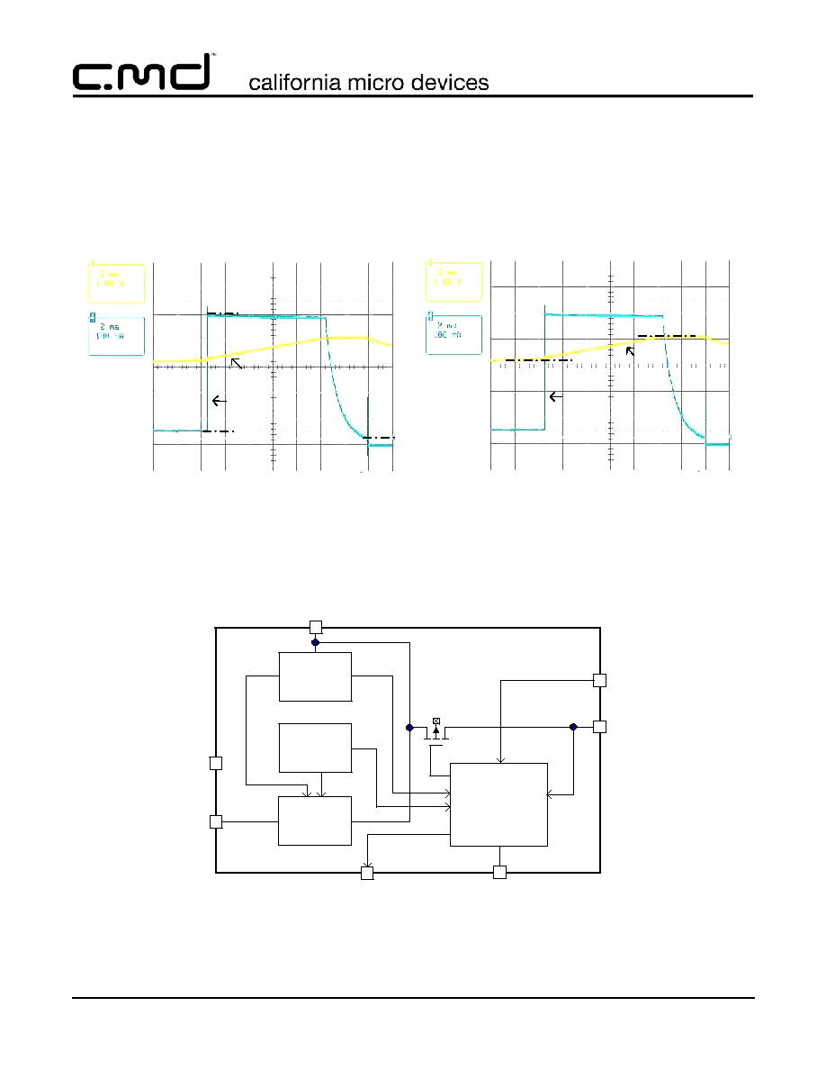
Functional Block Diagram
Time (2 ms/div)
Charging Algorithm
Battery Emulator, Cbattery = 30 mF
R
ISET
= 5 k
Battery Current Thresholds
Ichg_cc=500mA
Ichg_term=25mA
Ichg_pr=50mA
Battery voltage
Charge current
Time (2 ms/div)
Battery Voltage Thresholds
CC mode = 3.3V
CV mode = 4.2V
Charge current
Battery voltage
Qc
Charger
Control
OCP
Over-Temp
Limit
OTP
GND
VOUT
ISET
CM9100
STAT
VIN
LDO
VREF
Current
Limit
VSTB
Typical Performance Curves

©
2006 California Micro Devices Corp. All rights reserved.
6
490 N. McCarthy Blvd., Milpitas, CA 95035-5112
l
Tel: 408.263.3214
l
Fax: 408.263.7846
l
www.cmd.com
06/30/06
CM9100
PRELIMINARY
Set Precharge Mode
STAT=
ON
Tj > 150
o
C
Stop charging and Latch ;
Set STAT=OFF
VOUT
>
3.3V
Yes
Precharge
Mode
CC Mode
No
Yes
Set CV Mode
CV Mode
No
Yes
OTP
OCP
Yes
Standby
Mode
No
Charge Done
VIN
< VOUT
Stop Charging
Sleep mode
No
Yes
Yes
No
Stop charging
Set STAT=OFF
VOUT
< 4.200V-100 mV
VOUT
>= 4.200 V
Set CC mode
STAT
=ON
Set Precharge Mode
STAT=
ON
4.75V < VIN < 6.5V
Iin > 1A
No
I
CH
< Iterm
Flow Chart

©
2006 California Micro Devices Corp. All rights reserved.
06/30/06
490 N. McCarthy Blvd., Milpitas, CA 95035-5112
l
Tel: 408.263.3214
l
Fax: 408.263.7846
l
www.cmd.com
7
CM9100
PRELIMINARY
The CM9100 is an integrated charger with a charging
profile tailored for single-cell graphite electrode (anode)
Li-ion batteries. With single resistor charge current pro-
gramming, the CM9100 can provide charge currents
up to 1000mA, or limited to 100mA/500mA for USB
input applications.
The charger features the three modes required for a
safe and reliable Li-ion charging profile; Precharge,
Fast-charge, and Termination charge. Extensive safety
features include voltage and current monitoring. A sta-
tus indicator provides charge state information.
Linear Charger vs. Switching Charger
A Li-ion battery charger can be either a switching or a
linear regulator. A switching regulator type charger
achieves higher efficiency, typical 90% or better, over a
wide range of load and line conditions and generally
offers a faster charging speed. However, a switching
charger requires an external power inductor, which
occupies substantial PC board space with added
weight. Another issue with switching regulators is the
switching noise and the potential EMI it generates.
In contrast, The CM9100 linear charger is implemented
with a single IC, without the use of an inductor. The
CM9100 provides a complete Li-ion charging control
system, with integrated power MOSFETs and several
important features, requiring just a few external resis-
tors and capacitors for a compact system design. A
sophisticated thermal management system addresses
the concerns commonly associated with linear charg-
ers.
Input
When using a constant-voltage, 5VDC nominal, AC
adapter, the semi-regulated voltage to the charger,
after accounting for the conduction losses through the
power cord and connector contacts, is a voltage in the
range of 5.0V to 6.0V.
The USB standard specifies a 5.0V +/-5% bus voltage,
capable of 500mA (High Power peripheral configura-
tion) of current. When using a USB input, the charging
current must be limited to <500mA, which is set with
the R
SET
resistor. In a system that requires 100mA
starting current until told by the host controller to go
into High Power mode, the circuit in
Figure 1
can be
used. Q1 can be the output of the controller.
Figure 1. USB Input Circuit
Charging Li-ion Batteries
Once the CM9100 detects the presence of a valid AC
adapter, and checks that the battery voltage at V
OUT
is
less then V
IN
, it is ready to charge the Li-ion battery.
If the battery voltage is deeply discharged (less than
3.2V), the CM9100 will start in the Precharge mode,
charging at 10% of the programmed Fast-charge cur-
rent level. See
Figure 2
. While the battery is charging,
the status pins will be set to STAT=0. The Precharge
current will gradually bring the battery voltage to above
3.2V.
Figure 2. Typical Li-ion Battery Charging Process
Once the battery voltage exceeds the 3.3V threshold,
the CM9100 enters the Fast-charge, constant-current
(CC) mode. The status pins will be set to STAT=0. Dur-
ing the CC mode, the charging current is limited by the
maximum charging current, programmed with a single
resistor between I
SET
and ground, R
ISET
:
CM9100
VOUT
Charger
From
USB
100 mA
500 mA
Q1
nmos
VIN
ISET
25.5k
6.19k
4.0V
3.0V
2.0V
0.8A
0.4A
Charging
Current
Charging
Voltage
Pre-
Charge
CC
Mode
CV
Mode
I
FASTCHG
max
(
)
2.5V
1000
◊
R
ISET
--------------------------------
=
Application Information

©
2006 California Micro Devices Corp. All rights reserved.
8
490 N. McCarthy Blvd., Milpitas, CA 95035-5112
l
Tel: 408.263.3214
l
Fax: 408.263.7846
l
www.cmd.com
06/30/06
CM9100
PRELIMINARY
Most battery manufactures recommend an optimal
charging current for their battery. This is typically a time
ratio related to the battery capacity, with a value of .7C
to 1C, once the battery is above the Precharge voltage
level. For example, a 750mAh capacity battery with
recommended charge of .7C could have I
CC
set for
about 525mA, with R
ISET
equal to 4.75k
, 1%.
The actual Fast-charge current might be further limited
by either the maximum chip temperature limit, deter-
mined by the power dissipation on the CM9100 chip,
the ambient temperature (T
A
), and the junction-to-
ambient thermal resistance, Rth
(JA)
.
When the battery terminal voltage, sensed at V
OUT
,
approaches 4.2V, the CM9100 enters the Termination
(CV) mode. The charger then regulates its output volt-
age at 4.20V, and the charging current gradually
decreases as the battery's internal voltage, V
OC
, rises
toward 4.2V. The actual charging current is now deter-
mined by the differential voltage (4.20V ≠ V
OC
) and the
internal impedance, R
internal
, of the Li-ion battery-pack.
The CM9100 ends the charging process when charg-
ing current drops below 5% of the Fast-charge (CC)
mode current level. Once terminated, the charge cur-
rent is completely stopped and no trickle charge is
applied. Trickle (or float) charging is not required due to
the minimal self-discharge of the Li-ion cells, and they
are unable to absorb overcharge, which causes plating
of metallic lithium and shortens the life of the battery.
Following the Termination mode, the charger will enter
the Standby mode. The status pin will be set to
STAT=V
IN
.
If the wall adapter is left plugged-in while in the
Standby mode, the charger will continue to monitor the
battery voltage. It automatically re-charges the battery
when the battery voltage drops below the re-charge
threshold. When the adapter is removed, the CM9100
will drain less than 1µA from the battery.
Charging Current Foldback in the Over-
temperature Condition
A limitation of linear chargers is that they are vulnera-
ble to over-temperature conditions. The CM9100 will
throttle down the charging current when the chip junc-
tion temperature reaches 105∞C (with 10∞C of hystere-
sis). This protects the charger IC and its nearby
external components from excessive temperature.
The Charger IC junction temperature is determined by
several factors in the following equation:
(1)
The Rth
(JA)
is usually determined by the IC package
and the thermal resistance between the package and
the PC board. In particular, a SMD IC package relies
on the underlying PC board copper to move the heat
away from the junction. The key to reducing the ther-
mal resistance between the IC package and the under-
lying PC board is using a large copper (Cu) area for
solder attach and a large ground plane underneath the
charger IC to conduct the heat away.
The power dissipation (PD in equation 1) of a linear
charger is the product of input-output voltage differen-
tial and output current.
Highest power dissipation occurs when the battery at
its lowest level (3.2V), when it just starts in the Fast-
charge (CC) mode. Assuming V
IN
= 5.0V, V
BAT
= 3.2V,
I
CC
= 1A, the PD = (5V-3.2V) x 1A = 1.8W. Assuming
Rth
(JA)
= 50∞C/W, then -T = 1.8W x 50∞C/W = 90∞C. If
the ambient temperature (T
A
) is 35∞C, then the junction
temperature (T
J
) could reach 125∞C without over-tem-
perature current foldback.
With over-temperature (OT) current foldback, the
CM9100 will throttle down the charging current, allow-
ing the junction temperature will reach steady-state
equilibrium of 105∞C, which translates into 1.4W of
power dissipation, or 0.78A of charge current. As the
battery voltage rises during charging, the allowable PD
dissipation is increased. When the battery voltage
reaches 3.6V, a full 1.0A of charging current is allowed.
OTP and OCP
In addition to chip temperature regulation at 105∞C, the
CM9100 provides absolute over-temperature shutdown
protection. In the case of a malfunctioning charger con-
trol, high ambient temperature or an unexpectedly high
IC thermal resistance, Rth
(JA)
(for example, due to
faulty soldering of the charger IC chip). The CM9100
T
J
T
A
PD Rth
JA
(
)
+
+
=
PD
V
IN
V
OUT
≠
(
) I
OUT
◊
=
Application Information (cont'd)

©
2006 California Micro Devices Corp. All rights reserved.
06/30/06
490 N. McCarthy Blvd., Milpitas, CA 95035-5112
l
Tel: 408.263.3214
l
Fax: 408.263.7846
l
www.cmd.com
9
CM9100
PRELIMINARY
provides an absolute OTP shutdown at junction tem-
perature of 150∞C.
Charging status
CM9100 provides a charging status indicator pin: STAT.
This is an open-drain output, which can drive an LED
directly, with up to 20mA of current sinking capability.
Alternatively, the system supervisory microprocessor
can monitor the battery charging status by interfacing
with this pin, using a 100k
pull-up resistor. See
Table
1
.
Table 1: Charge Status for STAT
Charging Control by the Host System
The CM9100 allows a host-system to take active con-
trol of the charging process by providing actual charg-
ing current monitoring via the 1000:1 current mirror on
R
ISET
. This is especially useful for the system's direct
control of the Termination threshold (preset to 5% of
CC mode level).
Mode Summary
Precharge mode is the typical charge starting mode
for pre-conditioning a deeply discharged battery
(<3.3V). A constant current of 10% of the programmed
Fast-charge current is applied to raise the voltage
safely above 3.3V.
Fast-charge mode is the constant current charging
mode that applies most of the battery charge. A pro-
grammed constant current is applied to bring the bat-
tery voltage to 4.2V.
Termination mode is the final charging mode, where a
constant voltage of 4.2V is applied to the battery until
the charge current drops below 5% or the programmed
Fast-charge current.
Standby mode is entered after a successful Termina-
tion mode and charging is done. Charging stops. In this
mode, the battery is monitored, and when its voltage
drops below the re-charge threshold, a new charge
cycle begins.
Shutdown mode is triggered by a charging fault.
These include, Input current that exceeds 2.4A (OCP),
the IC junction temperature exceeds 150∞C (OTP).
Charging stops.
Sleep mode is entered when the Adapter is removed
(or is the wrong voltage). Charging stops. In this mode,
the CM9100 draws less than 1µA of current from the
battery.
Component Selection
The constant voltage AC Adapter must be selected
carefully to minimize power losses and heat dissipation
in the charger. The input supply should be between
5.0V and 6.0V. The lowest allowable input voltage will
minimize heat dissipation and simplify the thermal
design.
Layout Considerations
Because the internal thermal foldback circuit will limit
the current when the IC reaches 105∞C it is important
to keep a good thermal interface between the IC and
the PC board. It is critical that the exposed metal on
the backside of the CM9100 be soldered to the PCB
ground. The Cu pad should is large and thick enough
to provided good thermal spreading. Thermal vias to
other Cu layers provide improved thermal perfor-
mance.
V
IN
and V
OUT
are high current paths and the traces
should be sized appropriately for the maximum current
to avoid voltage drops.
CHARGE STATUS
STAT
Precharge in progress
Low -
Fast-charge in progress
Low -
Charge completed
High -
Charge suspended (OTP,
OCP)
High -
Application Information (cont'd)

©
2006 California Micro Devices Corp. All rights reserved.
10
490 N. McCarthy Blvd., Milpitas, CA 95035-5112
l
Tel: 408.263.3214
l
Fax: 408.263.7846
l
www.cmd.com
06/30/06
CM9100
PRELIMINARY
Li-ion
Battery
VIN
NC
NC VSTB
NC
NC
GND
VREF
ISET NC
NC
NC
STAT
NC
VOUT
NC
R5
5K
1
2
3
4
5
6
7
8
9
10
11
13
14
15
16
CM9100
+VBAT
THERM
T
H
ER
M
I
ST
O
R
R7
10K
R4
499
C2
0.1U
C1
4.7U
VIN
R6
500
D1
GLED
C3
4.7U
*
12
Typical Evaluation Circuit

©
2006 California Micro Devices Corp. All rights reserved.
06/30/06
490 N. McCarthy Blvd., Milpitas, CA 95035-5112
l
Tel: 408.263.3214
l
Fax: 408.263.7846
l
www.cmd.com
11
CM9100
PRELIMINARY
TQFN-16 Mechanical Specifications
The CM9100-00QE is supplied in a 16-lead, 4.0mm x
4.0mm TQFN package. Dimensions are presented
below.
For complete information on the TQFN16, see the Cal-
ifornia Micro Devices TQFN Package Information doc-
ument.
Package Dimensions for 16-Lead TQFN
PACKAGE DIMENSIONS
Package
TQFN-16 (4x4)
Leads
16
Dim.
Millimeters
Inches
Min
Nom
Max
Min
Nom
Max
A
0.07
0.75
0.80
0.28
0.030
0.031
A1
0.00
0.05
0.00
0.002
A3
0.20 REF
.008
b
0.25
0.30
0.35
0.010
0.012
0.014
D
3.90
4.00
4.10
0.154
0.157
0.161
D1
1.95 REF
0.077
D2
2.00
2.10
2.20
0.079
0.083
0.087
E
3.90
4.00
4.10
0.154
0.157
0.161
E1
1.95 REF
0.077
E2
2.00
2.10
2.20
0.079
0.083
0.087
e
0.65 TYP.
0.026
L
0.45
0.55
0.65
0.018
0.022
0.026
# per
tape and
reel
3000 pieces
Controlling dimension: millimeters
A3
A1
0.10 C
0.08 C
A
SIDE VIEW
Mechanical Package Diagrams
D
E
0.15 C
0.15 C
BOTTOM VIEW
TOP VIEW
e
b
L
0.10
C A B
M
16X
D2
E2
DAP SIZE
1.8 X 1.8
E1
D1
Pin 1 Marking
Mechanical Details