 | –≠–ª–µ–∫—Ç—Ä–æ–Ω–Ω—ã–π –∫–æ–º–ø–æ–Ω–µ–Ω—Ç: CM9101 | –°–∫–∞—á–∞—Ç—å:  PDF PDF  ZIP ZIP |

CM9101
PRELIMINARY
Compact Cost-effective Fast Charger
Features
∑
Monolithic linear charger requires no inductors,
external sense resistors or blocking diodes
∑
A few external components are required
∑
4.75V to 6.5V operating input voltage range.
∑
Battery temperature monitor with thermistor (NTC)
interface
∑
Programmable the charging current to achieve the
fastest charging rate without the risk of overloading
the adapter
∑
Thermal limit control of charging current prevents
overheating
∑
Maximum of 1µA battery drain current
∑
Charging-current monitor output for system super
vision of charging status
∑
TQFN-16, RoHS compliant lead-free package
Applications
∑
Cellular phones and smart phones
∑
PDAs Portable Media Viewers
∑
Digital Still Camera
∑
Cradle Chargers
Product Description
The CM9101 is an integrated linear-mode charger for
single-cell, Lithium-ion batteries. It designed for com
pact and cost-sensitive handheld devices. It provides
programming charge current, battery temperature
monitoring, charge status indicator, charge termina
tion, high accuracy fast charge current and automatic
charge voltage regulation. It requires no external block
ing diodes or current sense resistors and needs only
one external resistor to program the charging current.
The CM9101 provides Precharge, Fast-charge (con
stant-current), and Termination (constant-voltage)
charging modes. The Precharge/Termination currents
are preset to 10/5% of the Fast-charge current level. A
host system can monitor the actual charge current at
the ISET pin.
The battery temperature can continuously measured
by an external thermistor through the THERM pin.
When the chip temperature reach 140∞C, the CM9101
goes into a latched shutdown mode stop charging until
the chip temperature is below 140∞C will gradually
charge and 105∞C resume fast charge.
When the adapter is not present, the CM9101 draws
less than 1µA of drain current from the battery in ultra
low power sleep mode.
The CM9101 is packaged in a miniature 16-pin TQFN.
It can operate over the ambient temperature range of
40∞C to 85∞C.
Typical Application
Li-ion
Battery
10k
Vout
GND
VOUT
THERM
VIN
BSEN
Vin
4.7u
5k
ISET
STAT
CM9101
VREF
0.1u
1k
VSTB
1u
4.7u
4k
ENA
©
2006 California Micro Devices Corp. All rights reserved.
06/30/06
490 N. McCarthy Blvd., Milpitas, CA 95035-5112
l
Tel: 408.263.3214
l
Fax: 408.263.7846
l
www.cmd.com
1
PRELIMINARY
CM9101
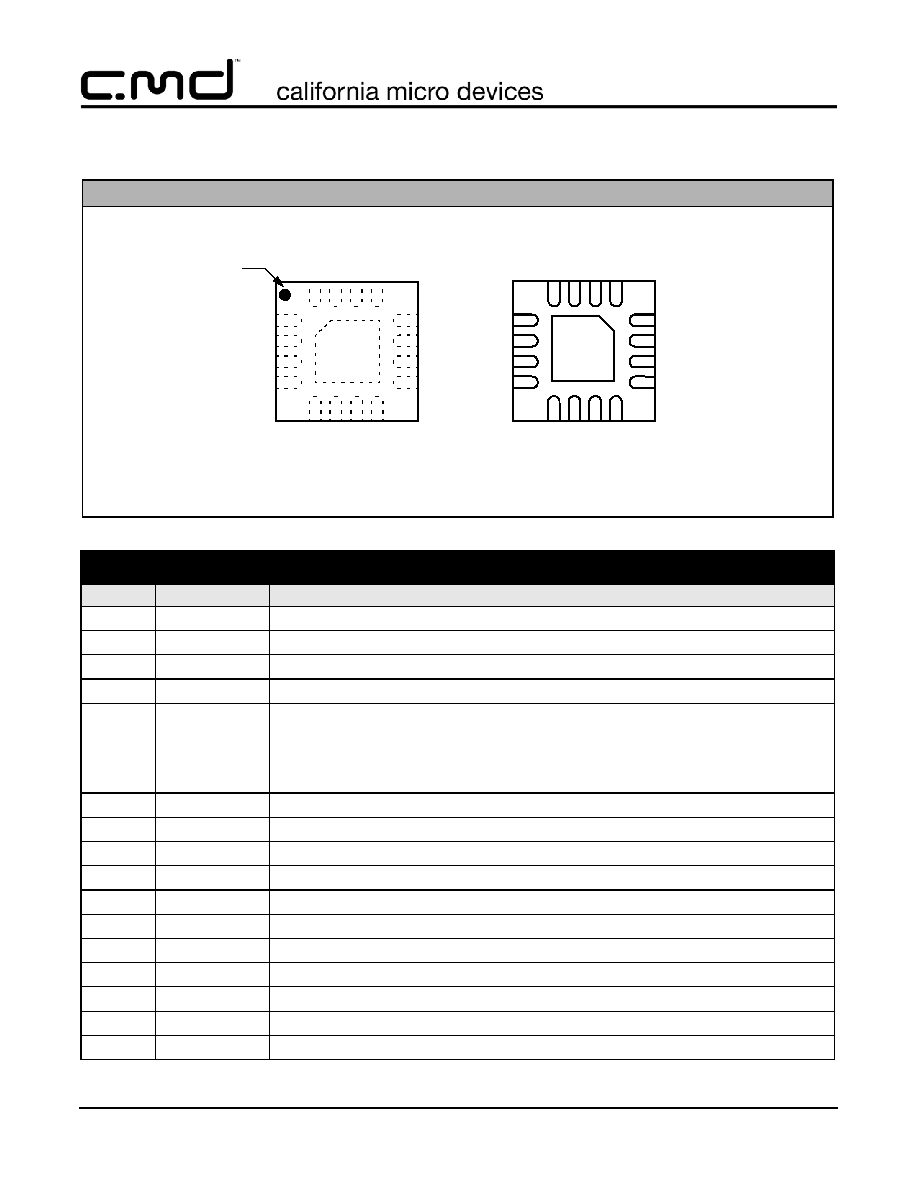
Package Pinout
PACKAGE / PINOUT DIAGRAM
CM9101-00QE
4
3
2
1
9
10
11
12
5
6
7
8
16
15
14
13
GND
PAD
BOTTOM VIEW
(Pins Up View)
TOP VIEW
(Pins Down View)
VREF
NC
GND
NC
STAT
THERM
VOUT
BSEN
VI
N
NC
NC
VS
TB
IS
ET
ENA
NC
NC
4
3
2
1
9
10
11
12
5
6
7
8
16
15
14
13
CM91
00
00QE
Pin 1
Marking
16-Lead TQFN Package (4mm x 4mm)
Note: This drawing is not to scale.
PIN DESCRIPTIONS
LEAD(s)
NAME
DESCRIPTION
1
NC
No connect.
2
GND
Ground pin.
3
NC
No connect.
4
VREF
4.2V, 2 mA reference output pin.
5
ISET
Pin to set the maximum charging current in the Fast charge (CC) mode. Also, reflects actual
charging current. A resistor between this pin and ground sets the charge current, I
CH
:
R
ISET
1000
◊ 2.5V
I
CC
-
= -----------------------------
6
ENA
Enable pin. Logic high (default value) enables charging. Logic low disables charging.
7
NC
No connect.
8
NC
No connect.
9
STAT
Charging status indicator pin (open-drain output).
10
THERM
Thermistor input pin from battery monitoring circuit.
11
VOUT
Charger output pin.
12
BSEN
Battery voltage remote sense pin.
13
VSTB
4.2V output pin, connect a cap to ground to increase stability.
14
NC
No connect.
15
NC
No connect.
16
VIN
Positive input supply voltage pin, which powers the charger.
©
2006 California Micro Devices Corp. All rights reserved.
2
490 N. McCarthy Blvd., Milpitas, CA 95035-5112
l
Tel: 408.263.3214
l
Fax: 408.263.7846
l
www.cmd.com
06/30/06

PRELIMINARY
CM9101
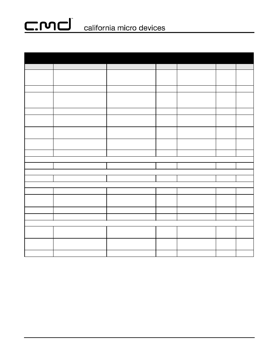
Ordering Information
PART NUMBERING INFORMATION
Pins
Package
Lead Free Finish
Ordering Part Number
1
Part Marking
16
TQFN
CM9101-00QE
CM9101 00QE
Note 1: Parts are shipped in Tape & Reel form unless otherwise specified.
Specifications
ABSOLUTE MAXIMUM RATINGS
PARAMETER
RATING
UNITS
ESD Protection (HBM)
±2
kV
V
IN
to GND
[GND - 0.3] to +6.5
V
Pin Voltages
V
OUT
, V
STB
to GND
ENA, I
SET
, STAT to GND
BSEN
,
THERM, V
REF
to GND
[GND - 0.3] to +6.5
[GND - 0.3] to +6.5
[GND - 0.3] to +6.5
V
V
V
Storage Temperature Range
-65 to +150
∞C
Operating Temperature Range (Ambient)
-40 to +85
∞C
Lead Temperature (Soldering, 10sec)
300
∞C
ELECTRICAL OPERATING CHARACTERISTICS
(SEE NOTE 1)
SYMBOL
PARAMETER
CONDITIONS
MIN
TYP
MAX
UNITS
V
IN
VIN Supply Voltage
V
IN
4.75
6.5
V
UVLO
UVLO Cut-in Threshold
All outputs are at no load
3.3
3.5
3.6
V
I
Q
Quiescent Current
Charging modes, exclud
ing current to I
SET
and
STAT pins. All outputs are
at no load.
2
mA
I
SHDN
Shutdown Supply Current
V
IN
= 5.0V, ENA = low,
excluding current to I
SET
and STAT pins.
50
100
µA
I
DR
Battery Drain Current
V
IN
= 0V (100
- resistor
to ground), V
BAT
= 4.2V
0.5
1
µA
Charger Function
I
PR
Precharge Mode Current
V
BSEN
< 3.2V
0.85 x I
PR
I
PR
250
R
SET k
( )
-
= -----------------------
1.14 x I
PR
mA
V
CC
CC Mode Voltage Threshold
3.20
3.30
3.40
V
©
2006 California Micro Devices Corp. All rights reserved.
06/30/06
490 N. McCarthy Blvd., Milpitas, CA 95035-5112
l
Tel: 408.263.3214
l
Fax: 408.263.7846
l
www.cmd.com
3
PRELIMINARY
CM9101
Specifications (cont'd)
ELECTRICAL OPERATING CHARACTERISTICS
(SEE NOTE 1)
SYMBOL
PARAMETER
CONDITIONS
MIN
TYP
MAX
UNITS
I
CC
CC Mode Charging Current, V
BSEN
> 3.5V
0.92 x I
CC
I
CC
2500
R
SET k
( )
-
= -----------------------
1.08 x
I
CC
mA
V
CV
CV Mode Voltage Threshold
4.190
4.200
4.210
V
I
TERM
Charge Termination Current V
BSEN
> 4.190V
0.8 x
I
TERM
I
TERM
100
R
SET k
( )
-
= -----------------------
1.2 x
I
TERM
mA
V
RCH
Recharge Mode Threshold
4.090
4.100
4.110
V
CT
Constant-temperature
Mode, Limit
(Note 2)
95
105
125
C
OTP
LIMIT
Over-temperature Protec
tion, Limit
(Note 3)
130
140
150
C
OCP
LIMIT
Over-current Charging
(OCP), Limit
(Note 4)
0.9
1.0
1.1
A
R
DSON
R
DSON
of Charger MOSFET I
CC
= 500mA
100
120
150
m
VREF
V
REF
Regulated Voltage V
REF
I
REF
< 1mA
4.190
4.200
4.210
V
VSTB
V
STB
Regulated Voltage V
STB
4.100
4.200
4.300
V
Control Function
I
BSEN
BSEN Pin Leakage Current V
IN
= 0
0.2
1.0
µA
V
STAT
STAT (Open Drain) Output
Low Voltage
I
SINK
= 5mA
I
SINK
= 20mA
0.1
0.5
V
V
V
IH EN
ENA Input High Level
1.5
V
V
IL EN
ENA Input Low Level
0.4
V
Thermistor Function (Note 4, 5)
V
BH
Battery HOT Voltage
Threshold (THERM Pin)
V
IN
= 5.0V
(Note 6)
0.9 x V
BH
V
BH
= 0.5 x V
IN
1.1 x V
BH
V
V
BC
Battery COLD Voltage
Threshold (THERM Pin)
V
IN
= 5.0V
(Note 6)
0.9 x V
BC
V
BC
= 7/8 x V
IN
1.1 x V
BC
V
Hysterezis of V
BH
, V
BC
80
100
120
mV
Note 1: V
IN
= 5.0V. All outputs are on. T
A
= 25∞C unless otherwise specified.
Note 2: When chip temperature reaches 105∞C, the IC's internal thermal limit will maintain this temperature by decreasing the pro
grammed charge current.
Note 3: When chip temperature reaches 140∞C, the IC goes into a latched shutdown mode. It stops charging, stops supplying
V
OUT
). To resume the charging function, a toggle of V
IN
is required.
Note 4: This feature can be disabled by connecting the THERM pin to GND.
Note 5: This function requires a Thermistor connected between the THERM pin and GND. Another resistor connected between
THERM pin and V
IN
is required, its value should equal the Thermistor Hot Value (at 50∞C). In order to catch both the 0∞C
and 50∞C thresholds (typical range for Li-ion battery) use Thermistors following 7/1 ratio (Thermistor COLD/Thermistor
HOT=7).
Note 6: If the battery HOT/COLD detection identifies a condition outside the thresholds, the IC stops charging the battery and waits
for the temperature to return to the normal value.
©
2006 California Micro Devices Corp. All rights reserved.
4
490 N. McCarthy Blvd., Milpitas, CA 95035-5112
l
Tel: 408.263.3214
l
Fax: 408.263.7846
l
www.cmd.com
06/30/06

CM9101
PRELIMINARY
Typical Performance Curves
Charging Algorithm
Battery Emulator, Cbattery = 30 mF
R
ISET
= 5 k
Ichg_cc=500mA
Ichg_term=25mA
Ichg_pr=50mA
Battery voltage
Charge current
CC mode = 3.3V
CV mode = 4.2V
Charge current
Battery voltage
Time (2 ms/div)
Time (2 ms/div)
Battery Current Thresholds
Battery Voltage Thresholds
Functional Block Diagram
VIN
Current
Limit
Qc
Charger
Control
OCP
Over-Temp
Limit
OTP
GND
VOUT
THERM
ENA
CM9101
BSEN
LDO
VREF
VSTB
STAT
ISET
©
2006 California Micro Devices Corp. All rights reserved.
06/30/06
490 N. McCarthy Blvd., Milpitas, CA 95035-5112
l
Tel: 408.263.3214
l
Fax: 408.263.7846
l
www.cmd.com
5