©
2006 California Micro Devices Corp. All rights reserved.
04/26/06
490 N. McCarthy Blvd., Milpitas, CA 95035-5112
l
Tel: 408.263.3214
l
Fax: 408.263.7846
l
www.cmd.com
1
CM9132
PRELIMINARY
Features
∑
2.9V to 6V input voltage range
∑
Powers two display backlight and/or flash WLED
∑
Low external parts count, requires no inductor and
ballast resistors
∑
Low EMI and reflected ripple
∑
Adaptive charge pump ratio (1x or 1.5x) maximizes
efficiency at both high and low input voltage
∑
Precision regulation for each output with 2% cur-
rent matching at 20
-
mA
∑
Programmable LED current via ISET1 and ISET2
∑
Independent Analog and PWM brightness control
∑
Independent current setting for each group
∑
Typical 500
-
KHz fixed switching frequency
∑
Supports up to 300
-
mA, drives five LEDs regulated
to 50
-
mA each
∑
Less than 10
-
µ
A shutdown current
∑
Over-current and over-temperature protection
∑
Short circuit protection with auto shutdown
∑
Undervoltage lockout
∑
Soft-start limits start-up inrush current
∑
TQFN-16 package
∑
Optional RoHS compliant lead free packaging
Applications
∑
Drive white LEDs for STN/TFT Color LCD back-
lighting
∑
Cell phones, PDAs with multiple displays
∑
Digital Still Cameras
∑
Flash for DSC
Product Description
The CM9132 is an adaptive fractional switched capaci-
tor (charge pump) regulator optimized for driving two
groups, 3 and 2, of white LEDs. Each group features
an individual ON/OFF control and individually set cur-
rent. Each LEDs driver current is matched to within 2%
for uniform intensity. It supports an input voltage range
of 2.9V to 6V, with undervoltage lockout. A failure
detection circuit prevents the loss of power when one
or more LEDs fail (short or open). Internal over-tem-
perature and over-current management provide short
circuit protection.
The CM9132 regulates up to 300
-
mA of output current
to drive WLEDs, allowing up to 50
-
mA per LED chan-
nel. The maximum LED current for each group is pro-
grammed with external resistors. Master plus two
independent enable inputs, allows for Analog and
PWM brightness control for each display. Either dis-
play can also be used for a camera flash. In full shut-
down mode, the CM9132 draws only 10
-
µ
A.
The CM9132 automatically selects the most efficient
charge pump ratio based on the operating voltage
requirement of the white LEDs. The proprietary design
architecture maintains high efficiency (> 80%), and at
low V
IN
provides longer battery life. With a high V
IN,
or
when the adapter is powered, it provides cool reliable
operation.
The CM9132 is available in a compac,t 16-pin TQFN
package. It can operate over the industrial temperature
range of -40 ∞C to 85 ∞C.
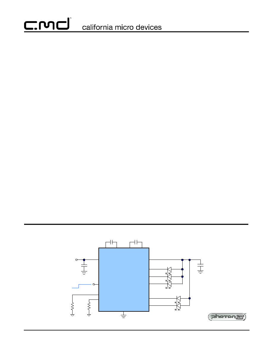
R
SET2
R
SET1
CM9132
VOUT
LED1
VIN
LED2
LED3
1.0uF
2.9V to 6.0V
1.0uF
1uF
C1P C1N
C2P C2N
LED4
LED5
GND
1uF
Display 1
Display 2
EN
ISET1
ISET2
Enable
on
off
PhotonIC
TM
Typical Application
Two Group, 3 and 2, WLED Driver, Different Current Settings

©
2006 California Micro Devices Corp. All rights reserved.
2
490 N. McCarthy Blvd., Milpitas, CA 95035-5112
l
Tel: 408.263.3214
l
Fax: 408.263.7846
l
www.cmd.com
04/26/06
CM9132
PRELIMINARY
Ordering Information
Note 1: Parts are shipped in Tape & Reel form unless otherwise specified.
Specifications
PACKAGE / PINOUT DIAGRAM
Note: This drawing is not to scale.
Bottom View
16-Lead TQFN Package
(4mm x 4mm)
ISET1
VIN
C1P
LED1
EN
GND
C1N
NC
LE
D2
VO
U
T
LE
D3
C2P
ISE
T
2
LE
D4
LE
D5
C2
N
4
3
2
1
9
10
11
12
5
6
7
8
16
15
14
13
TQFN16
4 X 4
PART NUMBERING INFORMATION
Leads
Package
Lead-free Finish
Ordering Part Number
1
Part Marking
16
TQFN
CM9132-01QE
ABSOLUTE MAXIMUM RATINGS
PARAMETER
RATING
UNITS
ESD Protection (HBM )
± 2
kV
Pin Voltages
V
IN
to GND
V
OUT
to GND
ISET1, ISET2, EN to GND
All other pins to GND
[GND - 0.3] to +6.0
[GND - 0.3] to +7.0
[GND - 0.3] to +5.0
[GND - 0.3] to +5.0
V
V
V
V
Storage Temperature Range
-65 to +150
∞C
Operating Temperature Range
-40 to +85
∞C
Lead Temperature (Soldering, 10s)
300
∞C
Package Pinout

©
2006 California Micro Devices Corp. All rights reserved.
04/26/06
490 N. McCarthy Blvd., Milpitas, CA 95035-5112
l
Tel: 408.263.3214
l
Fax: 408.263.7846
l
www.cmd.com
3
CM9132
PRELIMINARY
ELECTRICAL OPERATING CHARACTERISTICS
V
IN
= 3.6V; All outputs are on. Typical values are at T
A
= 25∞C.
SYMBOL
PARAMETER
CONDITIONS
MIN
TYP
MAX
UNIT
S
V
IN
Supply Voltage Range
2.9
6.0
V
V
UVLO
Undervoltage Lockout
All outputs are no load.
1.7
1.8
1.9
V
I
Q
Quiescent Current
1x mode
500
A
I
SD
Shutdown Supply Current
V
EN
< 0.4V
2
10
A
VOUT Charge Pump
V
OUT
Output Voltage
I
OUT
= 0mA to 120mA,
V
IN
= 3.0 to 5.5V
4.2
5.5
V
I
LED TOT
Total I
LED
Current
I
LED1
thru I
LED3
+photoflash
300
mA
ILED
Accuracy of ISET
V
IN
= 3.0V to 5.5V
1
%
Matching current between LED1
to LED3
V
IN
= 4.0V, I
LED 1,2,3
= 20mA
2
5
%
I
LED
per driver
Device total I
LED
< 150mA
50
mA
EN, ISET(1,2)
V
IH
High Level Input Voltage
1.8
V
IL
Low Level Input Voltage
0.4
Protection
Over-current Limit
400
mA
Over-temperature Limit
135
∞C
Over-temperature Hysteresis
15
∞C
Specifications (cont'd)
©
2006 California Micro Devices Corp. All rights reserved.
4
490 N. McCarthy Blvd., Milpitas, CA 95035-5112
l
Tel: 408.263.3214
l
Fax: 408.263.7846
l
www.cmd.com
04/26/06
CM9132
PRELIMINARY
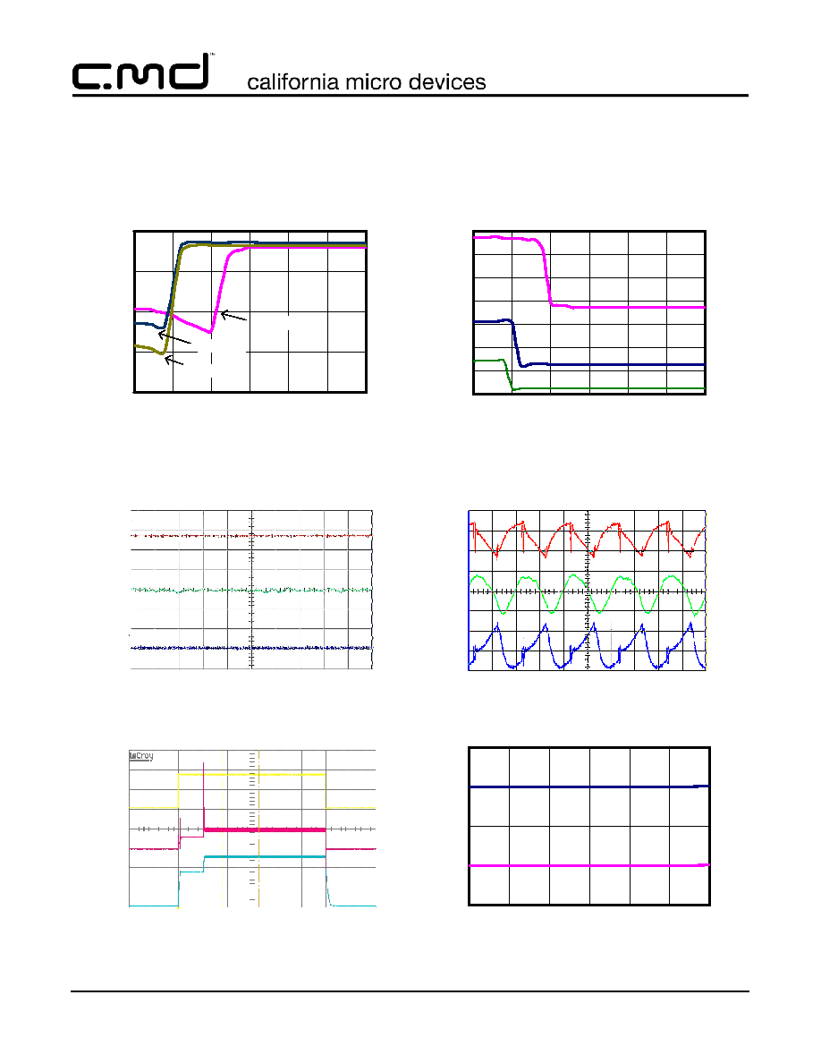
100 mV/
div
Iin
Vout
Vin
20mA/
div
50mV/
div
1us/div
Typical Waveforms
Cin=C2=C3=Cout=1uF, Iout=120mA
1.5x mode
100 mV/
div
20mA/
div
50mV/
div
Iin
Vout
Vin
1us/div
1.0x mode
Typical Waveforms
Cin=C2=C3=Cout=1uF, Iout=120mA
LED Current vs. Vin
5
10
15
20
25
3.0
3.5
4.0
4.5
5.0
5.5
6.0
Input Voltage (V)
LE
D
C
ur
r
e
n
t
(
m
A
)
Vout
EN
.5ms/div
Startup
Cin=C2=C3=Cout=1uF, Iout=120mA
1V/
div
200mA/
div
2V/
div
Iout=120mA
Iout=60mA
Iout=30mA
Source Current
25
50
75
100
125
150
175
200
3.0
3.5
4.0
4.5
5.0
5.5
6.0
Input Voltage (V)
In
pu
t
C
u
r
r
e
nt
(
m
A
)
Vled=3.2V
Charge Pump Efficiency
60
70
80
90
100
3.0
3.5
4.0
4.5
5.0
5.5
6.0
Input Voltage (V)
E
f
f
i
ci
en
cy
(
%
)
Vled=3.2V
Iout=30mA
Iout=60mA
Iout=120mA
Iin
Typical Performance Curves

©
2006 California Micro Devices Corp. All rights reserved.
04/26/06
490 N. McCarthy Blvd., Milpitas, CA 95035-5112
l
Tel: 408.263.3214
l
Fax: 408.263.7846
l
www.cmd.com
5
CM9132
PRELIMINARY
Pin Descriptions
VOUT
VIN
C1P
UVLO
OSC
500 KHz
Charge Pump x1, x1.5
C1N
C2P C2N
LED1
LED2
Current
Sinks
Bandgap
CM9132
Mode Select
Failed LED
Condition
LED3
LED4
LED5
EN
ISET1
GND
ISET2
PIN DESCRIPTIONS
LEAD(s)
NAME
DESCRIPTION
1
LED1
Cathode of LED1 pin.
2
C1P
This pin is the plus side of charge pump bucket capacitor C1. Connect a 1.0
-
µ
F
ceramic capacitor with a voltage rating of 10 V or greater between C1N and C1P.
3
VIN
Positive supply voltage input pin. This voltage should be between 2.9V and 6V.
This pin requires a 1.0
-
µ
F or larger ceramic capacitor to ground.
4
ISET1
Current set and shutdown pin for group one drivers, active low. Pull high to
shutdown the group.
To set the LED current, a resistor, R
SET
, is connected between this pin and ground.
The regulated LED current is 1000x the current flowing in R
SET
, and is
approximately;
If this resistor is tied to directly ground (and enable function not used) Logic Low =
0, otherwise subtract the voltage drop of the device that drives this pin low.
I
LED
0.66V
LogicLow
(
)
≠
R
SET
----------------------------------------------------- 1000
◊
=
Functional Block Diagram