
FEATURES
s
Maxim Compatible
s
3.3V and 5V Versions
s
Isolation to 4kV
s
Frequency Range to 500kHz
s
Toroidal Construction
s
Industrial Standard Pinout
s
UL 94V-0 Package Material
s
Fully Encapsulated
s
Low Profile
s
Surface Mount Available
DESCRIPTION
The 78253 series of converter transformers
are specifically designed for use with the
MAX253 chip set to provide isolated power
supplies. The 5V version can supply 1W and
the 3.3V version can supply 500mW. A
centre tapped secondary winding allows for
full bridge, half bridge or voltage doubling.
The surface mount devices are fully
compatible with CECC00802 to 280∞C
which allows them to be placed and reflowed
with IC's thus reducing time and cost in
production.
78253/35(M) CHARACTERISTICS
Parameter
Conditions
MIN
TYP
MAX
Units
Primary Inductance, L
P
100kHz, 250mV
0.30
0.38
0.46
mH
Secondary Inductance, L
S
100kHz, 250mV
1.60
2.00
2.40
mH
Leakage Inductance, L
L
100kHz, 250mV
0.30
1.00
µH
Interwinding Capacitance, C
WW
100kHz, 250mV
30
50
pF
D.C. Resistance, R
DC
>0.1VDC
0.40
1.00
Volt-time Product, E
T
5kHz, 5V
50
80
Vµs
78253/55(M) CHARACTERISTICS
Parameter
Conditions
MIN
TYP
MAX
Units
Primary Inductance, L
P
100kHz, 250mV
0.60
0.83
1.10
mH
Secondary Inductance, L
S
100kHz, 250mV
1.10
1.40
1.70
mH
Leakage Inductance, L
L
100kHz, 250mV
0.35
1.00
µH
Interwinding Capacitance, C
WW
100kHz, 250mV
30
50
pF
D.C. Resistance, R
DC
>0.1VDC
0.70
1.50
Volt-time Product, E
T
5kHz, 5V
50
65
Vµs
78253/35(M)V CHARACTERISTICS
Parameter
Conditions
MIN
TYP
MAX
Units
Primary Inductance, L
P
100kHz, 20mV
110
142
185
µH
Secondary Inductance, L
S
100kHz, 20mV
550
710
850
µH
Leakage Inductance, L
L
100kHz, 250mV
3.00
5.00
µH
Interwinding Capacitance, C
WW
100kHz, 250mV
4.20
8.00
pF
D.C. Resistance, R
DC
>0.1VDC
0.30
0.50
Volt-time Product, E
T
5kHz, 5V
30
42
Vµs
78253/55(M)V CHARACTERISTICS
Parameter
Conditions
MIN
TYP
MAX
Units
Primary Inductance, L
P
100kHz, 20mV
190
240
310
µH
Secondary Inductance, L
S
100kHz, 20mV
350
444
540
µH
Leakage Inductance, L
L
100kHz, 250mV
5.20
8.00
µH
Interwinding Capacitance, C
WW
100kHz, 250mV
4.20
8.00
pF
D.C. Resistance, R
DC
>0.1VDC
0.40
0.60
Volt-time Product, E
T
5kHz, 5V
25
32
Vµs
Operating free air temperature range
≠40∞C to 85∞C
Storage temperature range
≠50∞C to 125∞C
Lead Temperature 1.5mm from case for 10 seconds
300∞C
Peak current I
PK
400mA
Isolation voltage 78253/XX(M) (flash tested for 1 second)
1500VDC
Isolation voltage 78253/XX(M)V (flash tested for 1 second)
4000VDC
ABSOLUTE MAXIMUM RATINGS
All specifications typical at T
A
= 2 5 ∞ C .
SELECTION GUIDE
Input
Output
Output
Isolation
Turns
Package
Voltage
Voltage
Current
Voltage
Ratio
Style
Order Code
(V)
(V)
(mA Max)
(VDC)
78253/35
3.3
5.0
100
1500
1:
5
DIP
78253/35M
SM
78253/55
5.0
5.0
200
1500
1:1.31
DIP
78253/55M
SM
78253/35V
3.3
5.0
100
4000
1:
5
DIP
78253/35MV
SM
78253/55V
5.0
5.0
200
4000
1:1.36
DIP
78253/55MV
SM
78253 SERIES
MAX253 Compatible Converter Transformers
www.dc-dc.com
78253 SERIES
MAX253 Compatible Converter Transformers
C&D Technologies (NCL) Ltd
Tanners Drive, Blakelands North
Milton Keynes MK14 5BU, England
Tel: +44 (0)1908 615232
Fax:+44 (0)1908 617545
email: info@cdtechno-ncl.com
www: http://www.dc-dc.com
C&D Technologies (NCL), Inc.
8917 Glenwood Avenue, Raleigh
NC 27612, USA
Tel: +1 (919) 571-9405
Fax: +1 (919) 571-9262
email: info@us.cdtechno-ncl.com
C&D Technologies (NCL) Limited reserve the right to alter or improve the
specification, internal design or manufacturing process at any time, without
notice. Please check with your supplier or visit our web site to ensure that
you have the current and complete specification for your product before use.
© C&D Technologies (NCL) Limited 2000
NMP 78253.2
No part of this publication may be copied, transmitted or stored in a
retrieval system or reproduced in any way including, but not limited to,
photography, photocopy, magnetic or other recording means, without prior
written permission from C&D Technologies (NCL) Limited.
Instructions for use are available from www.dc-dc.com
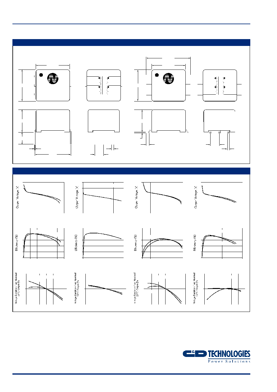
MECHANICAL DIMENSIONS
TYPICAL CHARACTERISTICS (VOLTAGE CURVES)
All dimensions in mm XX.XX ±0.25mm. All pins on a 2.54mm pitch and within ±0.25mm of true position.
6 Pin DIP
6 Pin SM
78253
35
9.52 max
8.89 max
1
2
3
Primary
Secondary
6
5
4
6.35
3.44±0.50
0.30
0.20
0.63
0.53
10.16
2.54
78250M
XYYWW
9.52 max
Top View
Top View
8.89 max
6.35
0.90
12.70
0.30
0.20
0.63
0.53
2.54
1
2
3
Primary
Secondary
6
5
4
XYYWW
0
20
40
60
80 100 120
Output Current (mA)
FS=High
FS=Low
78253/35(M)
10
8
6
4
2
0
0
100
200
300
400
Output Current (mA)
FS=Low/High
78253/55(M)
10
8
6
4
2
0
0
20
40
60
80
100
Output Current (mA)
FS=High
FS=Low
78253/35(M)V
10
8
6
4
2
0
0
100
200
300
400
Output Current (mA)
FS=High
FS=Low
78253/55(M)V
10
8
6
4
2
0
0
20
40
60
80 100 120
Output Current (mA)
FS=High
FS=Low
78253/35(M)
100
80
60
40
20
0
0
100
200
300
400
Output Current (mA)
FS=Low/High
78253/55(M)
100
80
60
40
20
0
0
20
40
60
80
100
Output Current (mA)
FS=High
FS=Low
78253/35(M)V
100
80
60
40
20
0
0
100
200
300
400
Output Current (mA)
FS=Low
FS=High
78253/55(M)V
100
80
60
40
20
0
-50 -25
0
25
50
75 100
Temperature (∞C)
FS=Low
78253/35(M)
1 1 0
105
100
9 5
9 0
FS=High
-50
-25
0
25
50
75 100
Temperature (∞C)
FS=Low
78253/55(M)
1 1 0
105
100
9 5
9 0
FS=High
-50
-25
0
25
50
75 100
Temperature (∞C)
FS=Low
78253/35(M)V
1 1 0
105
100
9 5
9 0
FS=High
-50 -25
0
25
50
75 100
Temperature (∞C)
FS=Low
78253/55(M)V
1 1 0
105
100
9 5
9 0
FS=High
EFFICIENCY CURVES
VOLTAGE DEVIATION
VOLTAGE CURVES