DNX301 4/2002 REV B
Page 1
DESCRIPTION
The DNX301 is a compact 300 watt, multiple output power
supply. All outputs are fully isolated and regulated. Active
current sharing circuitry on Output #1, together with control
functions and alarm options, simplifies N+1 and redundant
applications. Fan and disk drive applications are handled by
the peak current ratings of the auxiliary outputs.
FEATURES
Fully Isolated Outputs
Low Profile: 9" x 4.85" x 2.00"
One, Two, Three and Four
Output Models
N+1 Current Sharing
Optional Fan Mounted On
Cover
Active Inrush Current Limiting
300 W
ATT
DC/DC P
OWER
S
UPPLY
DNX301
Product Data Sheet
AGENCY APPROVALS
See "Safety" section on page 2 for more information
Power Electronics Division, United States
3400 E Britannia Drive, Tucson, Arizona 85706
Tel: 800.547.2537 Fax: 520.295.4197
C&D Technologies, (NCL)
Milton Keynes MK14 5BU UK
Tel: +44 (0)1908 615232 Fax: +44 (0)1908 617545
Any data, prices, descriptions or specifications presented herein are subject to revision by C&D Technologies, Inc. without notice. While such information is believed to be
accurate as indicated herein, C&D Technologies, Inc. makes no warranty and hereby disclaims all warranties, express or implied, with regard to the accuracy or completeness
of such information. Further, because the product(s) featured herein may be used under conditions beyond its control, C&D Technologies, Inc. hereby disclaims all warranties,
either express or implied, concerning the fitness or suitability of such product(s) for any particular use or in any specific application or arising from any course of dealing
or usage of trade. The user is solely responsible for determining the suitability of the product(s) featured herein for user's intended purpose and in user's specific application.
C&D Technologies, Inc. does not warrant or recommend that any of its products be used in any life support or aviation or aerospace applications.
Website: http://www.cdpowerelectronics.com

DNX301 4/2002 REV B
Page 2
Remote Sense
Remote Sense is provided on Output #1 and will
compensate for 0.7V of line drop. Remote Sense leads
are protected against open, short and reversal.
Remote On/Off (Optional)
The power supply is turned on with a TTL logic `1' (or open)
signal and turned off by a switch closure or TTL logic `0'
referenced to (-) sense terminal. Consult the factory for
other options.
Over Voltage Protection
Output #1: 6.5V � 0.5 V
DC.
The power supply will latch off until AC power is cycled.
Over Current Protection
Individual current limit on all outputs. Automatic recovery
upon fault removal.
Active Inrush Current Limiting
Inrush current is independent of ambient temperature.
Transient Response
The peak output voltage excursion will not exceed 2% and
will recover within 1% in 200
�sec for a 25% load step
change.
Over Temperature Protection
Thermal switch turns off power supply if overheating occurs
and automatically restarts.
Safety
Safety certified to UL/CUL to 1950, File Number E131694
TUV to EN60950/IEC950.
Cooling
The unit is designed to operate with 30 CFM of airflow.
Input Specifications
Parameter
Conditions
Min
Typ
Max
Units
Operating Range
DC
36
48
72
V
DC
Inrush Current Limiting
36V
D
25
A
PK
72V
DC
50
A
PK
Efficiency
48 V
DC
, at full load
70
%
DNX301 4/2002 REV B
Page 3
Output Voltages and Maximum Rated Loads
OUTPUT #1
OUTPUT #2
OUTPUT #3
OUTPUT #4
MODEL NUMBER
V
OUT
I
MAX
V
NOM
I
MAX
/I
PK
V
NOM
I
MAX
/I
PK
V
NOM
I
MAX
DNX301-U3A
�5V
45A
� 12V
8A/10A
� 12V
8A/10A
-
-
DNX301-U3B
�5V
45A
� 15V
8A/10A
� 15V
8A/10A
-
-
DNX301-U4C
�5V
45A
� 12V
8A/10A
� 12V
8A/10A
� 5V
3.0A
DNX301-U4D
�5V
45A
� 12V
8A/10A
� 12V
8A/10A
� 24V
1.5A
DNX301-U4E
�5V
45A
� 12V
8A/10A
� 12V
8A/10A
� 12V
3.0A
DNX301-U4F
�5V
45A
� 15V
8A/10A
� 15V
8A/10A
� 5V
3.0A
DNX301-U4G
�5V
45A
� 15V
8A/10A
� 15V
8A/10A
� 24V
1.5A
DNX301-U4H
�5V
45A
� 15V
8A/10A
� 15V
8A/10A
� 12V
3.0A
Note: Maximum current ratings are for 10sec maximum. Total power not to exceed 300 watts.
Output Specifications
Parameter
Limits
Regulation
Line
� 0.03%
Load
�0.25%
Cross
�0.05%
Minimum Load
Output #1
3.0A
Auxiliary Outputs
0.1A
Parameter
Conditions
Min
Typ
Max
Units
Voltage Adustment Range
�5
%
PARD
20 MHz bandwidth
1
% P-P
Temperature
Operating
0
50
�C
Storage
-20
+85
�C
Temperature Coefficient (T
C
)
After half hour warm-up
� 0.02
%/�C
DNX301 4/2002 REV B
Page 4
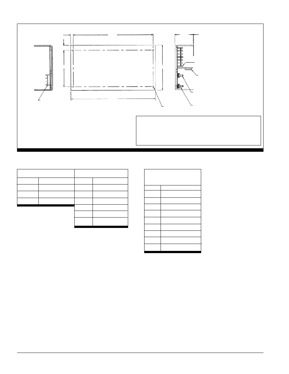
Mechanical
8.50
0.25
0.55
3.90
9.00
4.85
1.95
0.040
COVER
OUTPUT NO. 1
TB2
J9
5V RETURN
5V
6-32 THD 4 PLC'S
Maximum depth of mounting
scres is 0.156 inches
TB1
NOTES:
All measurements are in inches
FAN MOUNTED ON COVER ADDS 1.30".
COOLING: The DNX301 is designed to operate with 30 CM airflow.
SHOCK AND VIBRATION: The DNX301 meets the requirements of MIL STD-810D.
WEIGHT: Approximately 3 lbs.
TOP VIEW
Terminal Block 1
Terminal Block 2
POS
FUNCTION
POS
FUNCTION
1
DC +
1
-V2
2
DC -
2
+V2
3
Ground
3
-V3
4
+V3
5
-V4
6
+V4
J9 Connector
Molex No. 22-28-1090
PIN
FUNCTION
1
+ Sense
2
- Sense
3
N/C
4
N/C
5
Start Up Sync.
6
N/C
7
Remote Inhibit
8
Current Share
9
Control Signal Rtn
1
1
1