TX1000 2/2000 REV C
Page 1
FEATURES
Harmonic Correction to EN61000-3-2
Wide Range Input of 90-264V
AC
FCC / CISPR 22 Class A EMI Filtering
Typical Power Factor of 0.99
Active Current Sharing
Self-Cooled 5"x 4.88"x 12" Chassis
70-80% Efficiency
Optional ORing Diode
UL, CSA, and VDE compliant
CE Marked
EN61000-4 Immunity
AGENCY APPROVALS
Internet: http://www.cdpowerelectronics.com
Power Electronics Division, United States
3400 E Britannia Drive, Tucson, Arizona 85706
Phone: 800.547.2537 Fax: 520.770.9369
Power Electronics Division, Europe
C&D Technologies (Power Electronics) Ltd.
132 Shannon Industrial Estate
,
Shannon, Co. Clare, Ireland
Tel: +353.61.474.133
Fax:+353.61.474.141
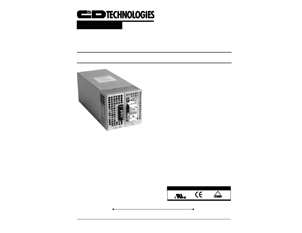
TX1000
1000 W
ATT
AC/DC P
OWER
S
UPPLY
Product Data Sheet
DESCRIPTION
The TX1000 Series of single-output, 1kW power
supplies are fully featured for usage worldwide. With
active Power Factor Correction (PFC) to EN61000-3-
2, wide-range input of 90-264V
AC
, EMI compliance to
FCC and CISPR 22, "CE" Mark, and immunity to
EN61000-4, the TX1000 series is ready for global
deployment. Standard features include remote sense
compensation, output voltage adjustment, active
current sharing, remote inhibit, power fail warning, DC
OK signal, and thermal shutdown. A complete array
of output voltages from 2.5 to 48V
DC
is available. The
self-cooled 5" x 4.88" x 12" chassis provides industry-
standard modularity that permits optimum flexibility in
installation. An optional ORing diode is offered on all
models greater than 5V
DC
models.

TX1000 2/2000 REV C
Page 2
Input Specifications
Parameters
Conditions
Min
Typ
Max
Units
Operating Range
47-63Hz
90
264
V
AC
Input Current
Nominal line, full load
12
A
Inrush Current
120V
AC
, 25
0
C, cold start
80
A
pk
240V
AC
, 25
0
C, cold start
160
A
pk
Efficiency
Nominal line, full load
70
75
80
%
Holdup
Full load
20
m
sec
Power Factor
(1)
Full load
0.99
Notes: (1) Harmonic currents meet EN61000-3-2
Output Voltages and Maximum Rated Loads
Model
Output Voltage
Output Current
TX10005AASLPLNH
5.0
200A
TX10005BASLPLNH
(1)
12.0
84A
TX10005CASLPLNH
(1)
15.0
67A
TX10005DASLPLNH
(1)
18.0
56A
TX10005EASLPLNH
(1)
24.0
42A
TX10005FASLPLNH
(1)
28.0
36A
TX10005GASLPLNH
(1)
36.0
28A
TX10005HASLPLNH
(1)
48.0
21A
TX10005JASLPLNH
(1)
20.0
50A
TXD10005KASLPLNH
(1)
3.3
182A
TXD10005LASLPLNH
(1)
2.5
200A
Notes: (1) Model specified without optional ORing diode; to specify the diode option, replace the letter "N" with the letter "D", no O-Ring diode on 5V models.
Output Specifications
Parameter
Conditions
Min
Typ
Max
Units
Output Power
All environmental and line conditions
1000
Watts
Voltage Adjustment Range
Relative to nominal output voltage
+5
%
Output Regulation
Line and load (each)
+0.2
%
Minimum Load
0
Amps
PARD
Measured at output terminals, 20MHz
1
% pk-pk
Temperature Coefficient
0
0
to 50
0
C
+0.2
%/
0
C
Environmental Specifications
Parameter
Conditions
Min
Typ
Max
Units
Ambient Temperature
Output de-rated linearly to 50% of
(Operating)
rated capacity between 50
0
C and 70
0
C
0
+70
0
C
Ambient Temperature
Non-operating
-50
+85
0
C
Altitude (Operating)
-200
+10,000
Feet
Altitude (Non-operating)
-200
+50,000
Feet
Shock
Per MIL-STD-810D, Method 516.3, Procedure II, in each axis, including NTSA drop test
Vibration
Per MIL-STD-810D, Method 514.3, Procedure II, in each axis, including NTSA drop test
Cooling
The TX1000 is provided with an internal cooling fan.

TX1000 2/2000 REV C
Page 3
The information provided herein is believed to be reliable; however, C&D TECHNOLOGIES assumes no responsibility for inaccuracies or omissions. C&D TECHNOLOGIES assumes
no responsibility for the use of this information, and all use of such information shall be entirely at the user's own risk. Prices and specifications are subject to change without notice.
No patent rights or licenses to any of the circuits described herein are implied or granted to any third party. C&D TECHNOLOGIES does not authorize or warrant any C&D TECHNOLOGIES
product for use in life support devices/systems or in aircraft control applications.
Product Features
Features
Characteristic
Remote Sense
500mV compensation
Active Current Sharing
Single Wire; 5% tolerance if outputs are over 25% of rated load
ORing Diode
Optional on all models (not available on 5V model)
OVP
125% of nominal (+7.5%)
Thermal Shutdown
Automatic Restart
DC OK Signal
Logic "1" when output is within +3% of nominal
Power Fail Warning Signal
Transition to Logic "0" at least 5msec before loss of output regulation
Remote Inhibit
Logic "0" applied will inhibit output (referenced to �Sense terminal)
Product Compliances
Approval
Characteristic
UL and cUL
UL1950, 3
rd
Edition
(1)
VDE
EN60950
FCC
Class A requirements for conducted emissions
CISPR 22
Class A requirements for conducted emissions
EN61000-4-2
Electrostatic Discharge, Level 4
EN61000-4-4
Electrical Fast Transients, Level 3
EN61000-4-5
Input Surge Immunity, Level 3
EN61000-3-2
Harmonic Currents, Class A
CE Mark
Low Voltage Directive
Notes: (1) UL1950, 3
rd
Edition incorporates the requirements of CSA 1950.
TX1000
Ordering Information
Model Designation
BASE MODEL
Chassis: "5" = 5" x 4.88" x 12"; "M" = modified
Output Voltage: See Chart below
Input Filter: "A" designates Class A EMI filter
Fan: "S" designates Standard Fan
Remote Inhibit: "L" designates that Logic "0" applied inhibits output
"P" designates Active Input Power Factor Correction with widerange input voltage of 90-264 V
AC
Power Fail Warning: "L" designates transition to Logic "0"
upon loss of AC
Output ORing diode: "N" = None; "D" = Diode Option
DC OK: "H" designates that Logic "1"
indicates a DC OK condition
OUTPUT VOLTAGES
A = 5V
G = 36V
B = 12V
H = 48V
C = 15V
J = 20V
D = 18V
K = 3.3V
E = 24V
L = 2.5V
F = 28V

TX1000 2/2000 REV C
Page 4
AIR FLOW
J1
J1
Pin Function Pin Function
No.
N
o
.
1 Remote Inhibit 10 N/C
2
DC
OK
9 - Sense
3
N
/
C
8
N
/
C
4
N/C
7 + Sense
5
P
o
wer
Fail
6 Current Share
.60
12.00
.19 MAX
4.88 +.000
-.170
10
9
2
1
3.000
1.00
8-32UNC-2B
.25 MAX. SCREW PENETRATION
4 PLACES
1.22
V ADJ
J1
PIN 1
5.00
.315
TYP
1.85
1.95
3.45
TB1
6-32 UNF-2A PHILSLOT
TORQUE TO 9 INCH/LBS MAX.
3 PLACES
1.00
1.60
1/4 - 20 UNC-2A
HEX HEAD SCREW
2 PLACES
6.375
MECHANICAL
J1 CONNECTOR
AMP NO. 87579-2 OR EQUIVALENT
PIN FUNCTION
NO.
1
REMOTE INHIBIT
2
DC OK
3
N/C
4
N/C
5
POWER FAIL
6
CURRENT SHARE
7
+ SENSE
8
N/C
9
_ SENSE
10
N/C