 | –≠–ª–µ–∫—Ç—Ä–æ–Ω–Ω—ã–π –∫–æ–º–ø–æ–Ω–µ–Ω—Ç: CMI8800 | –°–∫–∞—á–∞—Ç—å:  PDF PDF  ZIP ZIP |

cmi
Capella Microsystems Inc.
3777 Stevens Creek Blvd., Suite 320
Santa Clara, CA 95051-7364 U.S.A
Tel: (408) 260-3400
FAX: (408) 248-3416
Copyright © Capella Microsystems 1999 1
CONFIDENTIAL
CMI8800 Single/Three Phase
Spindle Motor Controller/Driver IC
For DVD/CD-ROM
PRELIMINARY DATA SHEET
Revision 3.0
07/09/99
This preliminary data sheet indicates that this product is still in the design cycle. All specifications
are based on design goals only. Capella Microsystems Inc. assumes no responsibility for the use of this
product.
Capella Microsystems Inc. reserves the right to make changes in specifications or discontinue
this product at any time without notice. Please contact Capella Microsystems Inc. for possible updates
before starting a design.
Capella Microsystems Inc. products are not designed for use in life support applications. Any
parties who use these products in such applications do so at their own risk and agree to fully indemnify
Capella Microsystems Inc. for any damages resulting from such improper usage or sale.

cmi
3777 Stevens Creek Blvd., Suite 320
Santa Clara, CA 95051-7364 U.S.A
Tel: (408) 260-3400
FAX: (408) 248-3416
Copyright © Capella Microsystems 1999 2
CONFIDENTIAL
GENERAL DESCRIPTION
The CMI8800 is a spindle motor
controller/ driver IC designed for DVD/CD-ROM
and Video CD (VCD) applications. This chip can
be used to control/drive single phase spindle
motors (see Page 20, Figure 17 for the
CMI8800 Application example) as well as
conventional three phase spindle motors. It
contains all of the necessary functional blocks
such as the hall bias generator, hall amplifier,
current limit amplifier, thermal shutdown, anti-
reverse protection, short brake, H-bridge power
driver and other functional blocks required for
motor controller/driver ICs (see Page 4, Figure 2
for the CMI8800 Simplified Block Diagram).
FEATURES
Brushless DC motor controller/driver IC
dedicated for DVD/CD-ROM and Video-CD
(VCD) spindle motor applications
Can drive both single phase spindle motors
as well as conventional three phase spindle
motors
Built-in hall bias generator and hall
amplifiers for easy interface with hall sensor
devices
Built-in sleep or start/stop mode to put the
chip and motor into sleep mode for power
saving
Built-in current limit amplifier to limit the
maximum allowed current into the motor
coil
Built-in thermal shutdown for overheat
protection
Built-in torque control to setup the motor's
torque according to the control voltage
applied to the EC and ECR pins
Built-in anti-reverse protection circuitry to
prevent the motor from going into the
opposite (reverse) rotation direction in the
constant linear velocity (CLV) operating
mode (used when the rotation speed is
decreased from the inner track to the outer
track)
Built-in frequency generator (FG) output as
well as rotation detect (FR) output circuitry
Built-in short brake circuitry to short all of
the motor coils and stop the motor quickly
Compatible with 3.3V digital signal
processor (DSP) interface
APPLICATIONS
DVD-DRIVES
CD-DRIVES
Absolute Maximum Ratings
(Ta = 25
∞
∞
C)
Description
Symbol
Value
Unit
Power Supply for Internal Core
VCCI
7
V
Power Supply for Motor Driver
VCCM1/VCCM2
16
V
Maximum Power Dissipation
Pd
1700*
mW
Storage Temperature
Tstg
-55 ~ 150
∞
C
Operating Temperature
Topr
-20 ~ 75
∞
C
Maximum Output Current
Iout
1300
mA
Hall Bias Current
IHB
50
mA
* 13.6mW/
∞
C Derating for Operating Temperature > 25
∞
C
(see Page 19, Figure 16 for the Derating Curve)
Recommended Power Supply Range
Description
Symbol
Value
Unit
Power Supply for Internal Core
VCCI
4.25 ~ 5.5
V
Power Supply for Motor Driver
VCCM1/VCCM2
3.0 ~ 15
V
cmi
3777 Stevens Creek Blvd., Suite 320
Santa Clara, CA 95051-7364 U.S.A
Tel: (408) 260-3400
FAX: (408) 248-3416
Copyright © Capella Microsystems 1999 3
CONFIDENTIAL
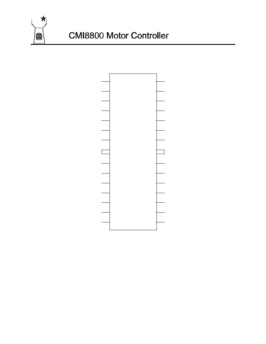
CMI8800
1
2
28
27
3
4
26
25
5
24
6
7
23
22
8
9
21
20
10
11
19
18
12
17
13
14
16
15
LDIN
RNF
W
VCCM1
LDOT
VCCM2
V
VCCI
N.C.
FG
N.C.
PS~
U
EC
FIN
FIN
GND
ECR
H1+
FR
H1-
1P/3P~
H2+
SB
H2-
CNF
H3+
BR
H3-
VH
Figure 1: CMI8800 Pin Assignment

cmi
3777 Stevens Creek Blvd., Suite 320
Santa Clara, CA 95051-7364 U.S.A
Tel: (408) 260-3400
FAX: (408) 248-3416
Copyright © Capella Microsystems 1999 4
CONFIDENTIAL
13
14
H3+
H3-
21
20
18
17
16
15
ECR
FR
SB
CNF
BR
VH
Hall Bias
Generator
H3+
H3-
MUX
In case of
Single Phase
11
12
H2+
H2-
Hall
Amp
8
9
10
GND
H1+
H1-
Hall
Amp
Hall
Amp
Hysteresis
Comp
H1+
H1-
H3+
H3-
Hysteresis
Comp
H2+
H2-
28
27
26
25
24
23
22
RNF
VCCM1
VCCM2
VCCI
FG
PS~
EC
Torque
Limit
VCCI
VCCI
CLK
Q~
D
Q
R
Communication
Control Logic
1
2
3
4
7
LDIN
W
LDOT
V
U
19
1P/3P~
Logic
Thermal
Shutdown
Torque
Sense Amp
Current
Limit Amp
+
-
Analog
Mux
A0
S
B1
+
-
Single Phase Motor -
Signal Processing
Circuitry
H-Bridge
Power
Driver
1P/3P~
Figure 2: CMI8800 Simplified Block Diagram
cmi
3777 Stevens Creek Blvd., Suite 320
Santa Clara, CA 95051-7364 U.S.A
Tel: (408) 260-3400
FAX: (408) 248-3416
Copyright © Capella Microsystems 1999 5
CONFIDENTIAL
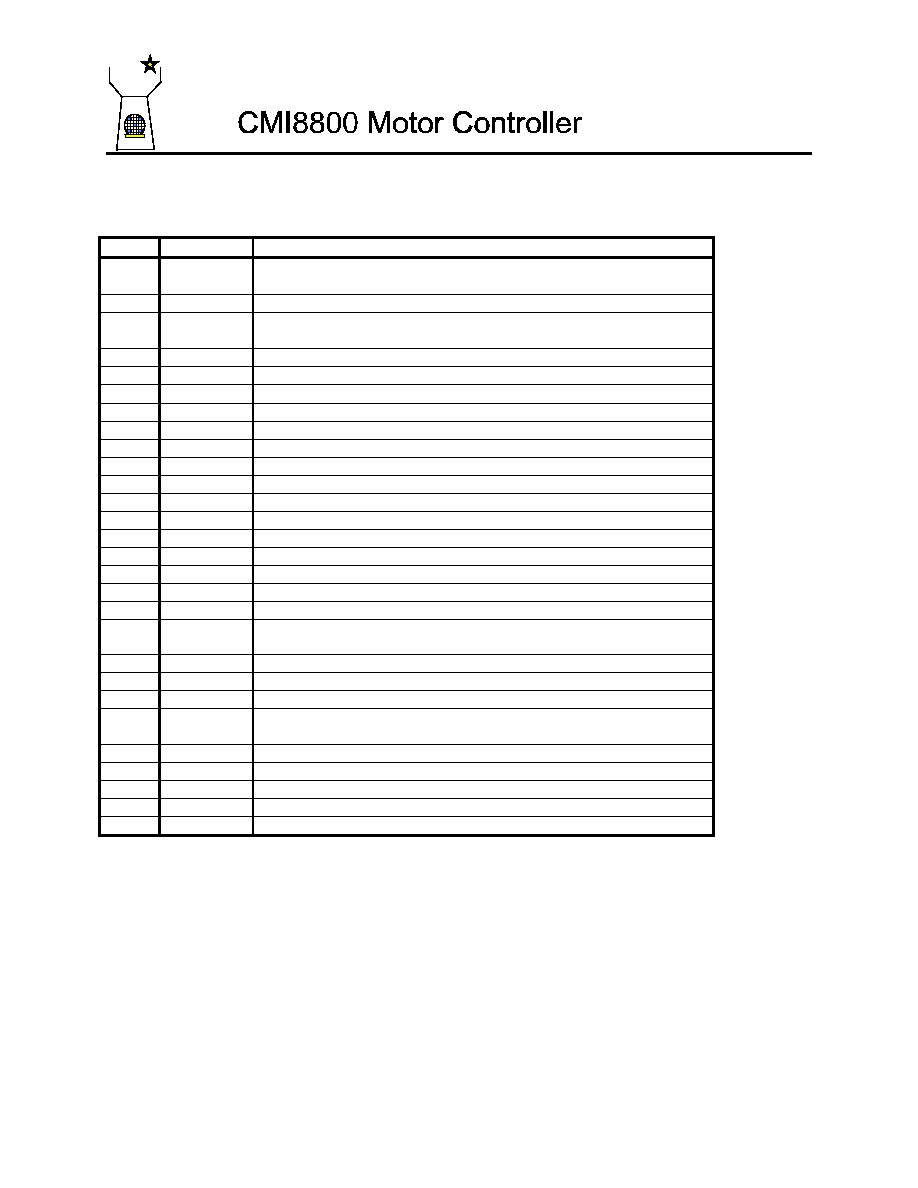
Pin Description
Pin #
Pin Name
Pin Description
1
LDIN
Input for the External Lead Network (for Single Phase Motor)
This Pin is left open for three phase motor applications
2
W
H-Bridge Power Driver Output (W)
3
LDOT
Output of External Lead Network (for Single Phase Motor)
This pin must be left open for three phase motor applications
4
V
H-Bridge Power Driver Output (V), NC for Single Phase Mode
5
NC
No Connection [This pin must be left open]
6
NC
No Connection [This pin must be left open]
7
U
H-Bridge Power Driver Output (U)
8
GND
Common Ground
9
H1+
Hall Amplifier #1 Positive Input
10
H1-
Hall Amplifier #1 Negative Input
11
H2+
Hall Amplifier #2 Positive Input
12
H2-
Hall Amplifier #2 Negative Input
13
H3+
Hall Amplifier #3 Positive Input
14
H3-
Hall Amplifier #3 Negative Input
15
VH
Hall Bias Generator Output (Open Collector Output)
16
BR
Brake Mode Control, High = Break Mode
17
CNF
Charge Pump Capacitor Between this Pin and Ground
18
SB
Short Brake Control Pin, High = Short Brake Mode
19
1P/3P~
Single Phase (1P)/Three Phase (3P) Control Pin
High = Single Phase. Default = Three Phase = Low
20
FR
Rotation Detection Pin
21
ECR
Reference Voltage to Torque Sense Amplifier
22
EC
Torque Control Input Terminal
23
PS~
Power Save or Sleep Mode Control
(Logic Low: Power Save or Sleeping Mode)
24
FG
FG Signal Output Pin
25
VCCI
5V Power Supply for Internal Core Circuitry
26
VCCM2
12V Power Supply for H-Bridge Motor (Power) Driver
27
VCCM1
12V Power Supply for Internal Core Circuitry
28
RNF
Motor Current Sense Resistor
Note: FIN
ý
ý
GND