 | –≠–ª–µ–∫—Ç—Ä–æ–Ω–Ω—ã–π –∫–æ–º–ø–æ–Ω–µ–Ω—Ç: AH2300A | –°–∫–∞—á–∞—Ç—å:  PDF PDF  ZIP ZIP |
Specifications are subject to change without notice WM23-96DS 080806
1
∑ Accuracy ±0.5 F.S. (current/voltage)
∑ Three-phase modular power analyzer
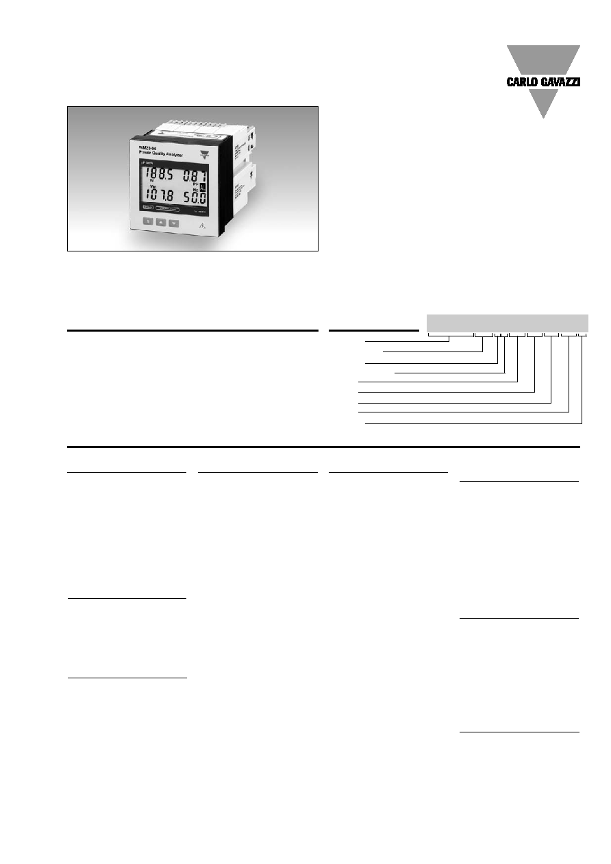
∑ Backlighted LCD 4x3 1/2 DGT Display
∑ Front size: 96x96 mm
∑ Measurements of phase and system variables: W, W
dmd
, var,
VA, VA
dmd
, PF, V
L-N
, V
L-L
, A, An, Hz, THD-A, THD-V
∑ TRMS measurement of distorted waves (voltages/currents)
∑ Measurement of MAX values: W L1, W L2, W L3, W, W
dmd
(AL1-AL2-AL3 max on request)
∑ Measurement of MIN values: PF L1, PF L2, PF L3, PF
∑ Harmonic analysis (FFT) up to the 16
th
harmonic (current
and voltage)
∑ Instantaneous variables read-out: 4x3 1/2 digit
∑ Up to 2 optional relay or open collector outputs
∑ 1 optional analogue output
∑ MODBUS, JBUS Protocol
∑ Protection degree (front): IP 65
∑ Universal power supply: 18-60VAC/VDC, 90-260 VAC/VDC
Product Description
µP-based three-phase mod-
ular power quality analyzer
with built-in programming
key-pad.
Particularly recommended for
a detailed analysis of the
electrical variables and of the
power quality. Housing for
panel mounting and IP65
(front) protection degree.
Energy Management
Modular Power Quality Analyzer
Type WM23-96
Type selection
Power supply
A:
24 VAC -15 +10%
50-60Hz
B:
48 VAC -15 +10%
50-60Hz
C:
115VAC -15 +10%
50-60Hz
D:
230 VAC -15 +10%
50-60Hz
L:
18 to 60VAC/VDC
H:
90 to 260VAC/VDC
Range code
AV4:
208VLL/5(6)AAC
-20%
Un +20%
AV5:
400VLL/5(6)AAC
-20%
Un +15%
AV6:
100VLL/5(6)AAC
-20%
Un +15%
AV7:
660VLL/5(6)AAC
-30%
Un +15%
50-60 Hz for all input mod-
ules. Module not removable.
∑ Phases asymmetry control
∑ Optional RS 232 serial port
∑ Optional RS 422/485 serial port
Slot C (redundant output or
digital inputs)
XX:
None
R1:
Single relay output
(AC1-8AAC, 250VAC)
R2:
Dual relay output
(AC1-8AAC, 250VAC)
O1:
Single open collector
output (30V/100mADC)
O2:
Dual open collector
output (30V/100mADC)
D1:
3 digital inputs
D2:
3 digital inputs +
aux output
Options
X:
None
S:
RS232 serial port
A:
displaying and record-
ing of AL1-AL2-AL3
max instead of WL1-
WL2-WL3 max.
Y:
Options: S+A above.
Model
Range Code
System
Power Supply
Slot A
Slot B
Slot C
Slot D
Options
Ordering Key
WM23-96AV53H XX XX XX XX X
System
3:
Three-phase,
unbalanced load,
with or without
neutral
Slot A (signal retransmission)
XX:
None
A1:
Single analogue output,
20mADC
A2:
Single analogue output,
±5mADC
A3:
Single analogue output,
±10mADC
A4:
Single analogue output,
±20mADC
B1:
Dual analogue output,
20mADC
B2:
Dual analogue output,
±5mADC
B3:
Dual analogue output,
±10mADC
B4:
Dual analogue output,
±20mADC
V1:
Single analogue output,
10VDC
V2:
Single analogue output,
±1VDC
V3:
Single analogue output,
±5VDC
V4:
Single analogue output,
±10VDC
W1:
Dual analogue output,
10VDC
W2:
Dual analogue output,
±1VDC
W3:
Dual analogue output,
±5VDC
W4:
Dual analogue output,
±10VDC
Slot B (communication)
XX:
None
S1:
Serial port,
RS485 multidrop,
bidirectional
Slot D (alarm output)
XX:
None
R1:
Single relay output,
(AC1-8AAC, 250VAC)
R2:
Dual relay output,
(AC1-8AAC, 250VAC)
O1:
Single open collector
output (30V/100mADC)
O2:
Dual open collector
output (30V/100mADC)
NOTE: with the A, B, C, D
types power supply, only
an open collector module
or a single relay output
module can be used.
The instrument can be ful-
ly equipped only with L
and H type power supply.
NOTE: the second ana-
logue output is intended
as redundant type only.
NOTE: max. digital output
(alarms and/or pulses): 2,
any exceeding output is
redundant.
2
Specifications are subject to change without notice WM23-96DS 080806
WM23-96
Insulation
By means of optocouplers,
4000 V
RMS
output to
measuring input
4000 V
RMS
output to
supply input
RS422/RS485
(on request)
Multidrop
bidirectional (static and
dynamic variables)
Connections
2 or 4 wires, max. distance
1200m, termination directly
on the instrument
Addresses
255, selectable by key-pad
Protocol
MODBUS/JBUS (RTU)
Data (bidirectional)
Dynamic (reading only)
System and phase variables:
see table "display pages"
Static (writing only)
All the configuration parameters,
activation of the static output.
Data format
1 start bit, 8 data bit,
no parity, 1 stop bit
Baud-rate
9600 bauds
Insulation
By means of optocouplers,
4000 V
RMS
output to
measuring input
4000 V
RMS
output to
supply input
RS232
(on request)
bidirectional (static and
dynamic variables)
Connections
3 wires, max. distance 15m,
Data format
1 start bit, 8 data bit
Analogue Outputs
(on request)
Number of outputs
Up to 1 (+1 redundant)
Accuracy
±0.2% f.s.
(@ 25∞C ±5∞C, R.H.
60%)
Range
0 to 20 mADC,
0 to ±20 mADC
0 to ±10 mADC,
0 to ±5 mADC
0 to 10 VDC,
0 to ±10 VDC
0 to ±5 VDC
0 to ±1 VDC
Scaling factor:
Programmable within the
whole range of retransmis-
sion; it allows the retrans-
mission management of all
values from: 0 and 20 mADC,
Variables
See relevant list
Response time
900 ms typical
(filter excluded, FFT excluded)
Ripple
1%
acc. to IEC 60688-1, EN 60688-1
Total temperature drift
500 ppm/∞C (input+out-
put)
Load:
20 mADC
600
±20 mADC
550
±10 mADC
1100
± 5 mADC
2200
10 VDC
10 k
±10 VDC
10 k
± 5 VDC
10 k
± 1 VDC
10 k
Number of analogue inputs
Current
3
Voltage
4
Digital Inputs
On request
AQ1038
Number of inputs: 3 ( voltage
free)
Use
Synchronization of the
W-VAdmd measurements
Input 1: lock of programming
Inputs 2 and 3: W-VA dmd
measurements synchronization
Reading voltage
24VDC/1mA
AQ1042
Number of inputs: 3 +
inputs power supply
Input frequency
Max 20Hz, dutycycle 50%
Output voltage
16V<+Aux<24VDC
Output current
Max 15mA
Open contact
resistance
Min 100k
Insulation
4000VRMS
Accuracy (display, RS232, RS485)
In=5A; Pn= In* Un
Un: F.S. range AV4-5-6-7
Current
±(0.5% In +2DGT)
Phase-neutral voltage
±(0.5% Un +2DGT)
Phase-phase voltage
±(1% Un +2DGT)
Frequency
±0.1Hz
Active power
(@ 25∞C ± 5∞C, R.H.
60%)
±(1% Pn +2DGT)
Reactive Power
(@ 25∞C ± 5∞C, R.H.
60%)
±(2% Pn +2DGT)
Apparent power
(@ 25∞C ± 5∞C, R.H.
60%)
±(1% Pn +2DGT)
Harmonic distortion
(@ 25∞C ± 5∞C, R.H.
60%)
±3% F.S. (up to 16
th
harmonic)
(F.S.: 100%)
Additional errors
Humidity
0.3% F.S. from 60% to 90% H.R.
Temperature drift
200ppm/∞C
Display
Back-lighted LCD 4x3
1
/
2
digit
70 x 38mm
Display refresh time
700ms
Measurements
Current, voltage, power, power
factor, frequency, harmonic
distortion. TRMS measure-
ment of a distorted wave.
Coupling type
Direct
Input impedance
208VLL 5(6)AAC (AV4):
>200 k
400VLL 5(6)AAC (AV5):
>900 k
100VLL 5(6)AAC (AV6):
>200 k
660VLL 5(6)AAC (AV7):
>900 k
Output Specifications
Input Specifications

Specifications are subject to change without notice WM23-96DS 080806
3
WM23-96
no parity, 1 stop bit
Baud-rate
9600 bauds
Protocol
MODBUS/JBUS (RTU)
other data
as per RS422/485
Digital outputs
(on request)
To be used as alarms or
remote control.
Alarm outputs
(on request)
Number of outputs
up to 2, independent
Alarm type
Up alarm, down alarm
Variables to be controlled
see the "List of the variables
that can be connected..."
Set-point adjustment
from 0 to 100% of the
electrical scale
Hysteresis
from 0 to 100% of the
electrical scale
On-time delay
0 to 255s
Relay status
Selectable, normally
de-energized and normally
energized
Output type
Relay, SPDT type
AC 1-8A @ 250VAC
DC 12-5A @ 24VDC
AC 15-2.5A @ 250VAC
DC 13-2.5A @ 24VDC
Min. response time
150 ms, filter excluded,
FFT excluded, setpoint
on-time delay: "0 s"
Insulation
By means of optocouplers,
4000 V
RMS
output to
measuring input,
4000 V
RMS
output to
supply input.
Note
The outputs can be either
relay type or open collector
type (V
ON
1.2VDC/Max.
100mA, V
OFF
30VDC Max.).
Insulation like relay outputs.
Output Specifications (cont.)
Page 5: PF L1(min),
PF L2 (min),
PF L3 (min)
Page 6: W L1, W L2, W L3
Page 7: W L1 (max),
W L2 (max),
W L3 (max)
Page 7: "A" option:
AL1 (max)
AL2 (max)
AL3 (max)
Page 8: var L1, var L2, var L3
Page 9: VA L1, VA L2, VA L3
Page 10: AL1 (alarm 1)
Page 11: AL2 (alarm 2)
Page 12: W
, PF, var, Hz
Page 13: W
, PF, VA, Hz
Page 14: W
(max), PF (min)
Page 15: W dmd, VA dmd, r.t.
Page 16: W dmd (max),
VA dmd (max)
Page 17: THD VL1, THD VL2,
THD VL3
Page 17: THD AL1,
THD AL2, THD AL3
Password
Numeric code of max
4 digits; 2 protection levels
of the programming data
1st level
Password "0", no protection
2nd level
Password from 1 to 1000, all
data are protected.
Transformer ratio
CT from 1 to 5000
VT from 1.0 to 1999, where
CT x VT
10000
Power demand (dmd)
Integration time
Programmable from 1 to 30 min
Filter
Filter operating range
From 0 to 100% of the
input electrical scale
Filtering coefficient
1 to 16
Filter action
Measurements, alarms, serial
port (fundamental variables:
V, A, W and their derived ones).
Page Variables
Up to 4 by page
Three-phase system with neutral
Page 1: V L1, V L2, V L3,
V LN
Page 2: V L12, V L13, V L31,
V
Page 3: A L1, A L2, AL3, An
Page 4: PF L1, PF L2,
PF L3, PF
Software Functions
AC voltage
90 to 260 VDC/VAC
18 to 60VDC/VAC
24 VAC -15+10% 50-60Hz
48 VAC -15+10% 50-60Hz
115VAC -15+10% 50-60Hz
230 VAC -15+10% 50-60Hz
Power consumption
30VA/12W (90 to 260V)
20VA/12W (18 to 60V)
Supply Specifications
4
Specifications are subject to change without notice WM23-96DS 080806
WM23-96
light industry environment
Immunity
EN 61000-6-2 (class A)
industrial environment
Other standards
Safety
IEC 61010-1, EN 61010-1
Product
IEC 60688-1, EN 60688-1
Approvals
CE, UL, CSA
Connections 5(6)A
Screw-type, max 2.5 mm
2
wires
(2 x 1.5mm
2
)
Housing
Dimensions
96x96x140 mm
Material
ABS, NORYL, PC (front)
self-extinguishing: UL 94 V-0
Protection degree
Front: IP65, NEMA4x, NEMA12
Connections: IP20
Weight
Approx. 400 g (packing incl.)
Operating temperature
0 to +50∞C (32 to 122∞F)
(R.H. < 90% non condensing)
Storage temperature
-10 to +60∞C (14 to 140∞F)
(R.H. < 90% non condensing)
Installation category
Cat. III (IEC 60664)
Pollution degree
2
Key-pad lock
by means of a rotary switch
placed behind the display or
by means of a contact (in
case of presence of the digital
inputs module)
Insulation
4000 V
RMS
between all
inputs/outputs to ground
Dielectric strength
4000 V
RMS
for 1 minute
EMC
Emissions
EN 61000-6-3 (class A)
residential, commercial and
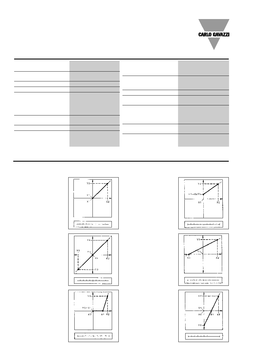
Function Description
Figure A
The sign of measured quantity
and output quantity remains
the same. The output quantity
is proportional to the mea-
sured quantity.
Input/analogue output scaling capability
Working of the analogue output (Y) versus the input variable (X) - (input/output scaling capability)
Figure B
The sign of measured quantity
and output quantity changes
simultaneously. The output
quantity is proportional to the
measured quantity.
Figure C
The sign of measured quantity
and output quantity remains
the same. From X0 to X1, the
output variable is 0. The range
X1...X2 is delineated on the
entire output range.
Figure F
The sign of the measured
quantity remains the same, that
of the output quantity changes
as the measured quantity
leaves range X0...X1 and pass-
es to range X1...X2.
Figure E
The sign of the measured
quantity changes but that of
the output quantity remains
the same. The output quantity
steadily increases from the
value X1 to the value X2 of the
measured quantity.
Figure D
The sign of measured quantity
and output quantity remains
the same. With the measured
quantity being zero, the output
quantity has the value
Y1 = 0.2 (live zero output).
0
50 A 100
A
0
10 mA 20
mA
-100 kW
0
100 kW
-10 mA
0
10 mA
80 V
100 V
120 V
0
5 mA 10
mA
0
50 A 100
A
4
12 mA 20
mA
-100 kW
0
100 kW
0
10 mA
20 mA
0
50 A 100
A
-1 V
0
1 V
General Specifications
Specifications are subject to change without notice WM23-96DS 080806
5
WM23-96
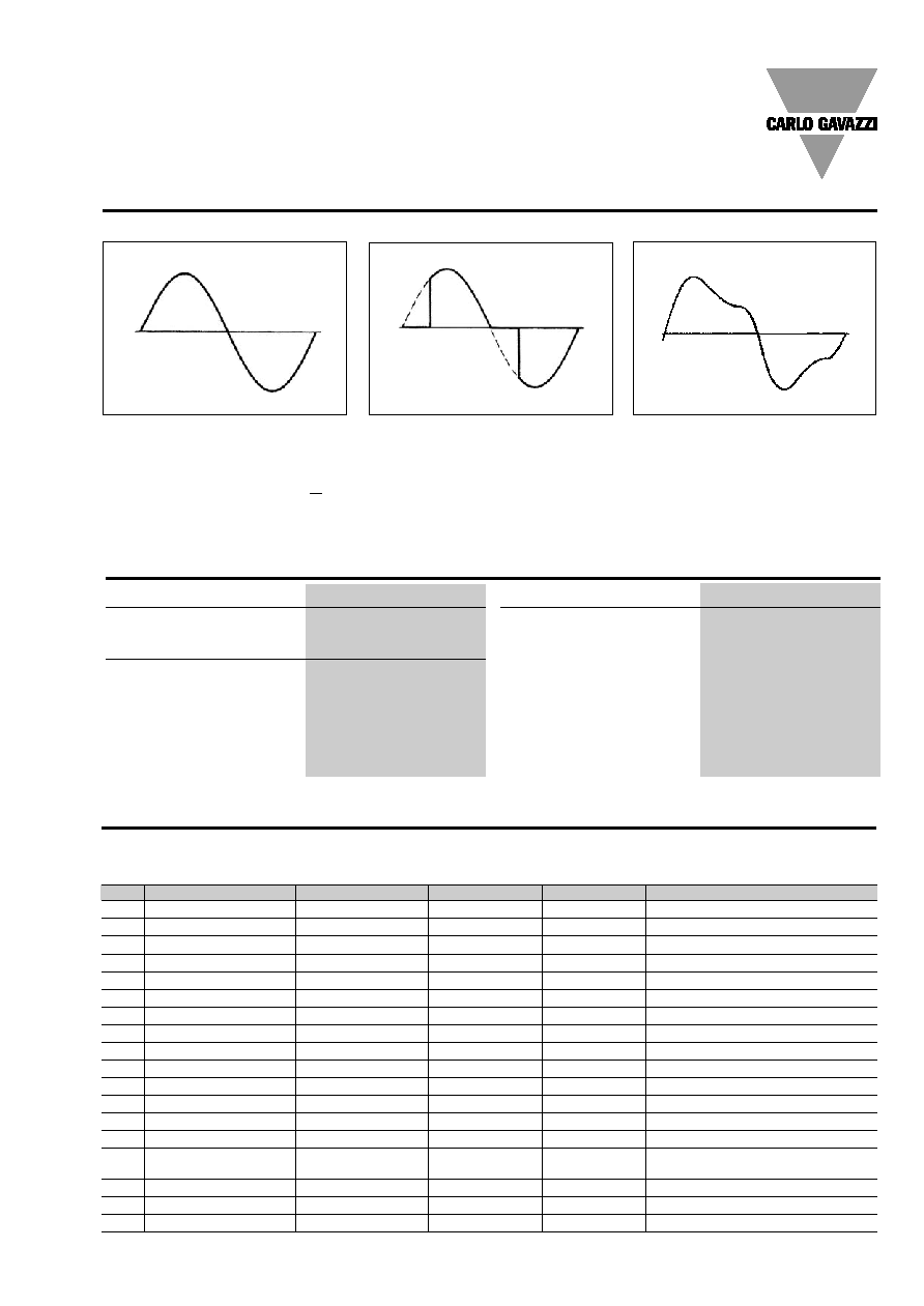
Waveform of the signals that can be measured
Figure G
Sinewave, undistorted
Fundamental content
100%
Harmonic content
0%
A
rms
=
1.1107 | A |
Figure H
Sinewave, indented
Fundamental content
10...100%
Harmonic content
0...90%
Frequency spectrum: 3rd to 16th harmonic
Figure I
Sinewave, distorted
Fundamental content
70...90%
Harmonic content
10...30%
Frequency spectrum: 3rd to 16th harmonic
Mode of operation
Analysis principle
FFT
Harmonic measurement
Current
Up to 16th harmonic
Voltage
Up to 16th harmonic
Type of harmonics
THD (V
L
1)
THD (V
L
2)
THD (V
L
3)
THD (A
L
1)
THD (A
L
2)
THD (A
L
3)
Display pages
THD %
Others
The harmonic distortion
can be measured in both
3-wire or 4-wire systems.
Harmonic Analysis
Variables that can be displayed in case of a three-phase system, 4-wire connection.
No
1st variable
2nd variable
3rd variable
4th variable Notes
1
V L1
V L2
V L3
V LN
= system
2
V L1-2
V L2-3
V L3-1
V
= system
3
A L1
A L2
A L3
An
An= neutral current
4
PF L1
PF L2
PF L3
PF
= system
5
PF L1 (min)
PF L2 (min)
PF L3 (min)
6
W L1
W L2
W L3
7
W L1 (max)
W L2 (max)
W L3 (max)
With "A" option: AL1-AL2-AL3 max
8
var L1
var L2
var L3
9
VA L1
VA L2
VA L3
10
AL 1
variable connected to alarm 1
11
AL 2
variable connected to alarm 2
12
W
PF
var
Hz
= system
13
W
PF
VA
Hz
= system
14
W
(max)
PF
(min)
= system
15
W dmd
VA dmd
r.t.
r.t.= symbol of communication
Rx/Tx on the serial port
16
W dmd (max)
VA dmd (max)
17
THD V L1
THD V L2
THD V L3
total harmonic distortion
18
THD A L1
THD A L2
THD A L3
total harmonic distortion
Display pages