Housing
Rated
Ordering no.
Ordering no.
diameter
operating
Cable
Plug
dist. (S
n
)
M18
20 mm
CA18CLC20BP
CA18CLC20BPM1
M 30
40 mm
CA30CLC40BP
CA30CLC40BPM1
Ordering Key
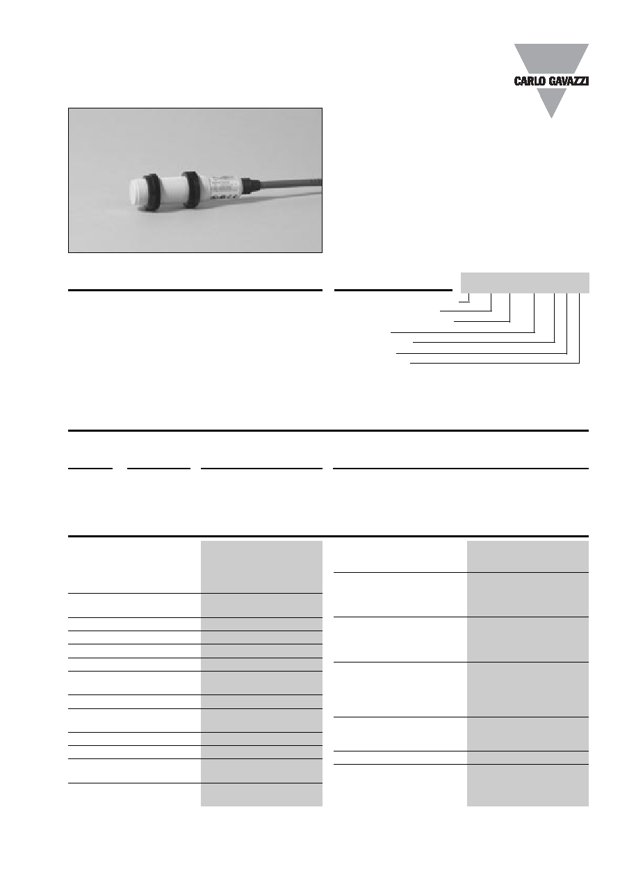
Product Description
Proximity Sensors Capacitive
Thermoplastic Polyester Housing
Types CA, M18, M30, DC
∑ Featuring
TRIPLESHIELDTM Sensor Protection
∑ Sensing distance: 0.1 - 20 mm (M18) and
0.1 - 40 mm (M30)
∑ Teach-in of sensing distance via pushbutton or Com-
input
∑ Automatic detection of NPN or PNP load
∑ Selectable make or break switching by means of
Teach-in function
∑ Protection: Short-circuit, transient and reverse polarity
∑ Dirt and moisture compensation
∑ Humidity compensation
∑ Alarm output
∑ 5 years of warranty
Capacitive proximity switch
Housing diameter (mm)
Rated operating dist. (mm)
Output type
Housing material
Housing type
Connection type
Type Selection
Capacitive proximity switch-
es with a sensing distance
of either 12 mm flush
mounted in metal or 20 mm
non-flush mounted for the
M18 version, and either 20
mm flush mounted in metal
or 40 mm non-flush mount-
ed for the M30 version. The
switching points can be
altered by means of the
Teach-in function. 3-wire DC
output with selectable make
(NO) or break (NC) switching
and NPN Alarm. Grey
polyester housing with 2 m
PVC cable or M12 plug.
TRIPLESHIELD
TM
CA18CLC20BPM1
Rated operating dist. (S
n
)
CA18CLC20
0.1 - 20 mm
factory set at 10 mm
CA30CLC40
0.1 - 40 mm
factory set at 20 mm
Sensitivity
Adjustable by means of
Teach-in
Effective operating dist. (S
r
)
0.9 x S
n
S
r
1.1 x S
n
Usable operating dist. (S
u
)
0.8 x S
r
S
n
> 1.2 x S
r
Repeat accuracy (R)
5%
Hysteresis (H)
Depending on Teach-in
Rated operational volt. (U
B
)
10 to 40 VDC
(ripple included)
Ripple
10%
Rated operational current (I
e
)
Continuous
250 mA
No-load supply current (I
o
)
12 mA)
Voltage drop (U
d
)
2.5 VAC at max. load
Protection
Short-circuit, reverse
polarity, transients
Frequency of operating
cycles (f)
15 Hz
Indication
For output ON
LED, yellow
For safe/unsafe
LED, green
Environment
Degree of protection
IP 68
Operating temperature
-20∞ to +85∞C ( -4∞ to +185∞F)
Storage temperature
-40∞ to +80∞C (-40∞ to +176∞F)
Housing material
Body
Grey, thermoplastic polyester
Cable end
Polyester, softened
Nuts
Black, PA12 Grilamid
Connection
Cable
Grey, 2 m, 4 x 0.34 mm
2
Oil proof, PVC
Plug (M1)
M12 x 1
Cable for plug (M1)
CON.1A-series
Weight
Cable version - M18 / M30
110 g/160 g
Plug version - M18 / M 30
30 g/70 g
Approvals
UL, CSA
CE-marking
Yes
Specifications
Specifications are subject to change without notice (25.03.02)
1
CA, M18, M30, DC
The environments in which
capacitive sensors are install-
ed can often be unstable re-
garding temperature, humidity,
object distance and industrial
(noise) interference. Because
of this, Carlo Gavazzi offers
as standard features in all
TRIPLESHIELDTM capacitive
sensors a user-friendly sensi-
tivity adjustment instead of
having a fixed sensing range,
extended sensing range to
Adjustment Guide
Installation Hints
Capacitive sensors have the
unique ability to detect al-
most all materials, either in li-
quid or solid form. Capacitive
sensors can detect metallic
as well as non-metallic ob-
jects, however, their tradition-
al use is for non-metallic
materials such as:
∑ Plastics Industry
Resins, regrinds or mould-
ed products.
∑ Chemical Industry
Cleansers, fertilisers, liquid
soaps, corrosives and pe-
trochemicals.
∑ Wood Industry
Saw dust, paper products,
door and window frames.
∑ Ceramic & Glass
Industry
Raw material, clay or
finished products, bottles.
∑ Packaging Industry
Package inspection for level
or contents, dry goods,
fruits and vegetables, dairy
products.
Materials are detected due to
their dielectric constant. The
bigger the size of an object,
the higher the density of ma-
terial, the better or easier it is
to detect the object. Nominal
sensing distance for a capaci-
tive sensor is referenced to a
grounded metal plate (ST37).
For additional information
regarding dielectric ratings
of materials please refer to
Technical Information.
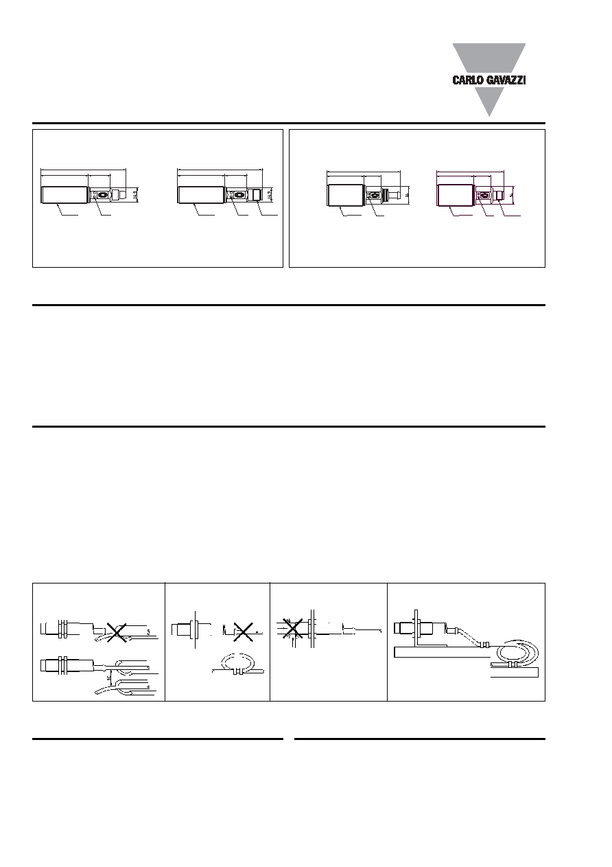
Dimensions
Relief of cable strain
Protection of the sensing face
Switch mounted on mobile carrier
To avoid interference from inductive voltage/
current peaks, separate the prox. switch pow-
er cables from any other power cables, e.g.
motor, contactor or solenoid cables
Not correct
Correct
The cable should not be pulled
A proximity switch should not serve as
mechanical stop
Any repetitive flexing of the
cable should be avoided
Plug
Cable
Plug
Cable
accommodate mechanically
demanding areas, temperature
stability to ensure minimum
need for adjusting sensitivity if
temperature varies and high
immunity to electromagnetic
interference (EMI).
Note:
Sensors are factory set
(default) to 50% of maximum
rated sensing range.
Specifications are subject to change without notice (25.03.02)
2
Delivery Contents
∑ Capacitive switch: CAxxCLCXXBPxx
∑ Packaging: Cardboard box
∑ Installation & Adjustment Guide (MAN CAP ENG/GER)
Accessories
∑ Plugs CONH6A.. series.
For further information please refer to "Accessories.
CA18
CA30
89.2
89.2
50
50
23
23
M18 x 1
LED
M12
89.55
89.55
50
50
23
23
M18 x 1
LED
99.2
50
23
M30 x 1.5
LED
90.45
50
23
M30 x 1.5
LED
M12 x 1
Specifications are subject to change without notice (20.08.01)
3
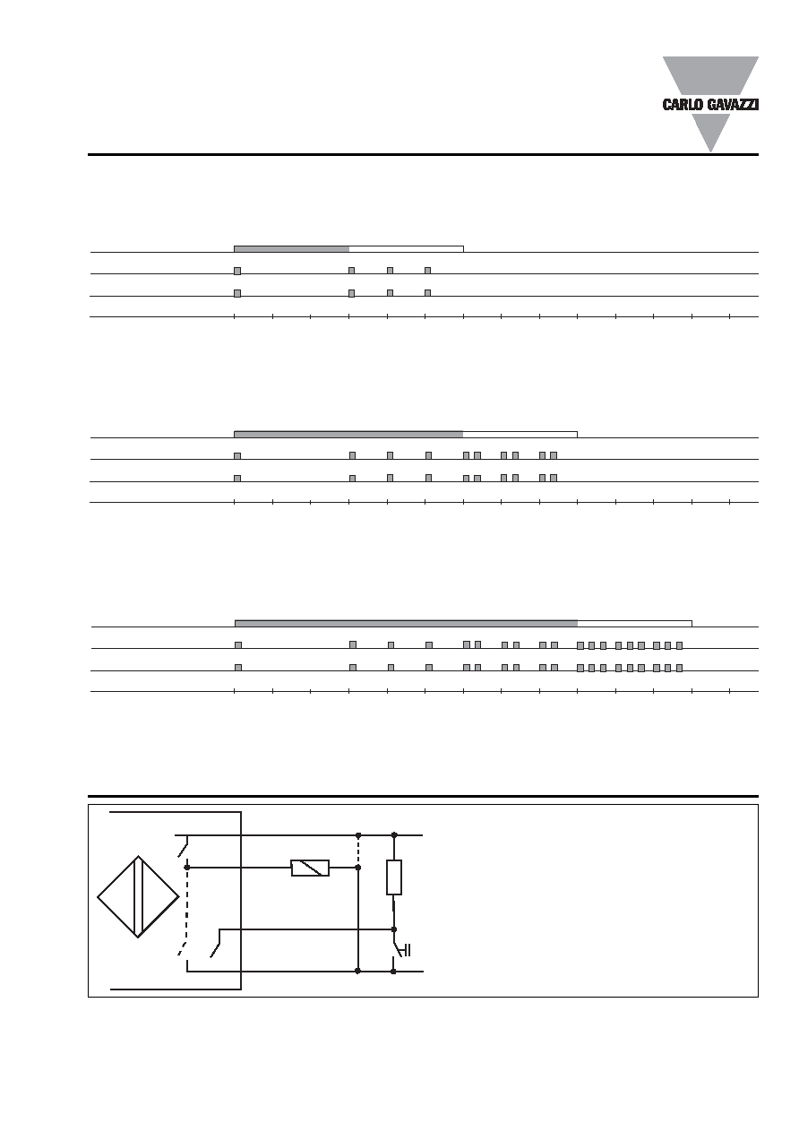
Teach-in Guide
Adjustment - Background
No target present
Pushbutton
LED - Green
LED - Yellow
Time (sec)
Press pushbutton >3 seconds until LED¥s are flashing one time per second. The background will be calibrated when the
pushbutton is released during the following 3 seconds
Adjustment - Object
Target present
Pushbutton
LED - Green
LED - Yellow
Time (sec)
Press pushbutton >6 seconds until LED¥s are flashing two times per second. The object will be calibrated when the pushbut-
ton is released during the following 3 seconds
Adjustment - NO - NC
Pushbutton
LED - Green
LED - Yellow
Time (sec)
0 1 2 3 4 5 6 7 8 9 10 11 12 13
Press pushbutton >9 sec. until LED¥s are flashing three times per second. The status of NO-NC will toggle when the pushbut-
ton is released during the following 3 seconds
BN+
BK
WH
BU-
Wiring Diagrams
I
LOAD
< 250mA
I
ALARM
< 20mA
Teach-in
The PNP- or NPN-load will automatically be
detected
By means of the Teach-in wire, the functions
described in the Teach-in Guide can be set-
up
It is possible to Teach-in more sensors at the
same time by connecting the WH-wires in
parallel to the common ˜ supply
(#): Plug connections
0 1 2 3 4 5 6 7 8 9 10 11 12 13
0 1 2 3 4 5 6 7 8 9 10 11 12 13
Releasing the pushbutton after 12 sec. returns the sensor to factory settings.
(1)
(3)
(2)
(4)