Specifications are subject to change without notice (27.12.99)
1
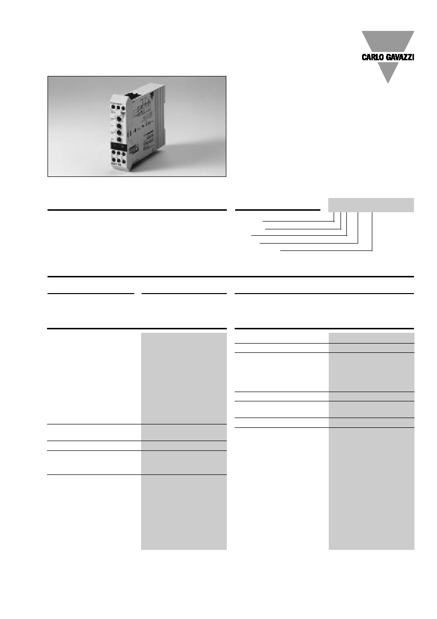
Asymmetrical Multi Recycler
∑ Microprocessor - based quartz timer
∑ Triple function timer
∑ Asymmetrical recycler (ON or OFF first)
∑ One shot time function
∑ Time range 0.1 s to 100 h
∑ Automatic start (ON or OFF time first)
∑ Separately knob adjustable time setting for T1 & T2
∑ Separately knob selection of time range for T1 & T2
∑ Repeatability deviation:
0.5%
∑ Output: 5A SPDT
∑ For mounting on DIN-rail in accordance with
DIN/EN 50 022
∑ 22.5 mm Euronorm housing
∑ LED-indication for relay and power supply ON
∑ Combined AC and DC power supply
Ordering Key
Housing
Function
Type
Output
Power supply
Triple-function timer, combi-
ned asymmetrical recycler
and one shot time function
with individual selection of ti-
me ranges (T1 & T2) from 0.1 s
to 100 h. For mounting on DIN-
rail. For use in many different
applications eg. lubricating
machines or switching on and
off electrical loads.
Product Description
Type Selection
Mounting
Output
Supply: 24 VAC/DC & 115-230 VAC
For DIN-rail
SPDT
ECC C T23
Time Specifications
Time ranges
T1 & T2
(individually adjustable)
Selectable by rotary switches 0.1 - 1 s
1 - 10 s
10 - 100 s
0.1 - 1 m
1 - 10 m
10 - 100 m
0.1 - 1 h
1 - 10 h
10 - 100 h
Accuracy
Time range accuracy
5%
Repeatability deviation
0.5%
Time variation
Within rated ambient
temperature
0.05%/∞C
Reset
Time and relay
Power supply interruption
200 ms
Output Specifications
Output
SPDT relay
Rated insulation voltage
250 VAC (contact/elect.)
Contact ratings (AgCdO)
µ (micro gap)
Resistive loads
AC 1
5 A, 250 VAC
DC 1
5 A, 24 VDC
Small inductive loads AC 15
2 A, 250 VAC
DC 13
3 A, 24 VDC
Mechanical life
40 x 10
6
operations
Electrical life
10
5
operations
(at max. load)
Operating frequency
7200 operations/h
Dielectric strength
Dielectric voltage
2 kVAC (rms)
Rated impulse withstand volt. 4 kV (1.2/50 µs)
Type ECC
Timers
ECC C T23

2
Specifications are subject to change without notice (27.12.99)
ECC
General Specifications
EMC
Electromagnetic
Compatibility
Immunity
acc. to IEC 60801-4
acc. to IEC 60801-5
Power ON delay
300 ms
Power OFF delay
200 ms
Indication for
Power supply ON
LED, green
Output ON
LED, yellow
Environment
Degree of protection
IP 20
Pollution degree
3
Operating temperature
-10∞ to +50∞C (-14∞ to +122∞F)
Storage temperature
-50∞ to +85∞C (-58∞ to +185∞F)
Weight
200 g
Screw terminals
Tightening torque
Max. 0.5 Nm acc. to IEC 60947
Approvals
UL, CSA
CE-marking
Yes
Supply Specifications
Power supply AC types
Overvoltage cat. III (IEC 60664)
Rated operational voltage
(IEC 60038)
through term. A1 & A2 T23
115-230 VAC, -10/+15%
frequency
50/60 Hz, -5/+5 Hz
through term. A2 & A3 T23
24 VAC/DC, -10/+15%
frequency
50/60 Hz, -5/+5 Hz
Voltage interruption
40 ms
Dielectric voltage
none
Rated impulse withstand
voltage
A1 & A2
4 kV (1.2/50 µs)
A2 & A3
800 V (1.2/50 µs)
Rated operational current
25 mA @ 24 VDC
40 mA @ 24 VAC
30 mA @ 115 VAC
60 mA @ 230 VAC
Mode of Operation
No connections between
Y1-Y2-Y3
OFF-time period first
The time period begins when
power supply is applied. At
the end of the first time period
(T1), the relay operates.
When the second time peri-
od (T2) has expired, the relay
releases.
This sequence continues until
power supply is interrupted
for at least 200 ms.
Connection between
Y1-Y3
ON-time period first
The relay operates and the
time period begins when
power supply is applied. At
the end of the first time period
(T1), the relay releases.
When the second time period
(T2) has expired, the relay op-
erates.
This sequence continues until
power supply is interrupted
for at least 200 ms.
Connection between
Y2-Y3
One shot time function
The time period begins when
power supply is applied. At
the end of the first time period
(T1), the relay operates.
When the second time period
(T2) has expired, the relay re-
leases.
The relay will stay OFF until
power supply is interrupted
for at least 200 ms, and the
sequence will be repeated.
Wiring Diagram
µ
L
N
Y
x
/A
x
Time Setting
Selection of time range (T1)
Upper knob:
10-position rotary switch.
Time setting (T1)
2nd upper knob:
Knob-adjustable on relative
scale 1-10.
Selection of time range (T2)
2nd lower knob:
10-position rotary switch.
Time setting (T2)
Lower knob:
Knob-adjustable on relative
scale 1-10.
24 V
~
115-230 V
~
Operation Diagram
Power supply
Y1-Y2-Y3 not conn. Relay ON
Y1-Y3 conn. Relay ON
Y2-Y3 conn. Relay ON