Specifications are subject to change without notice
1
∑
3 1/2-dgt meter or 3-dgt + dummy zero
∑
Temperature measurements from thermoresistance or
thermocouple probes and resistance measurements
∑
Measurements in ∫C or ∫F
∑
Indicator or controller
∑
All functions selectable by key-pad
∑
Password protection
∑
48 x 96 mm
∑
Degree of protection: IP 50 (IP 65 on request)
Product Description
Model
Range code
Power supply
Setpoints
Engineering unit
Option
Ordering Key
LDI35CFX D0 XX XX
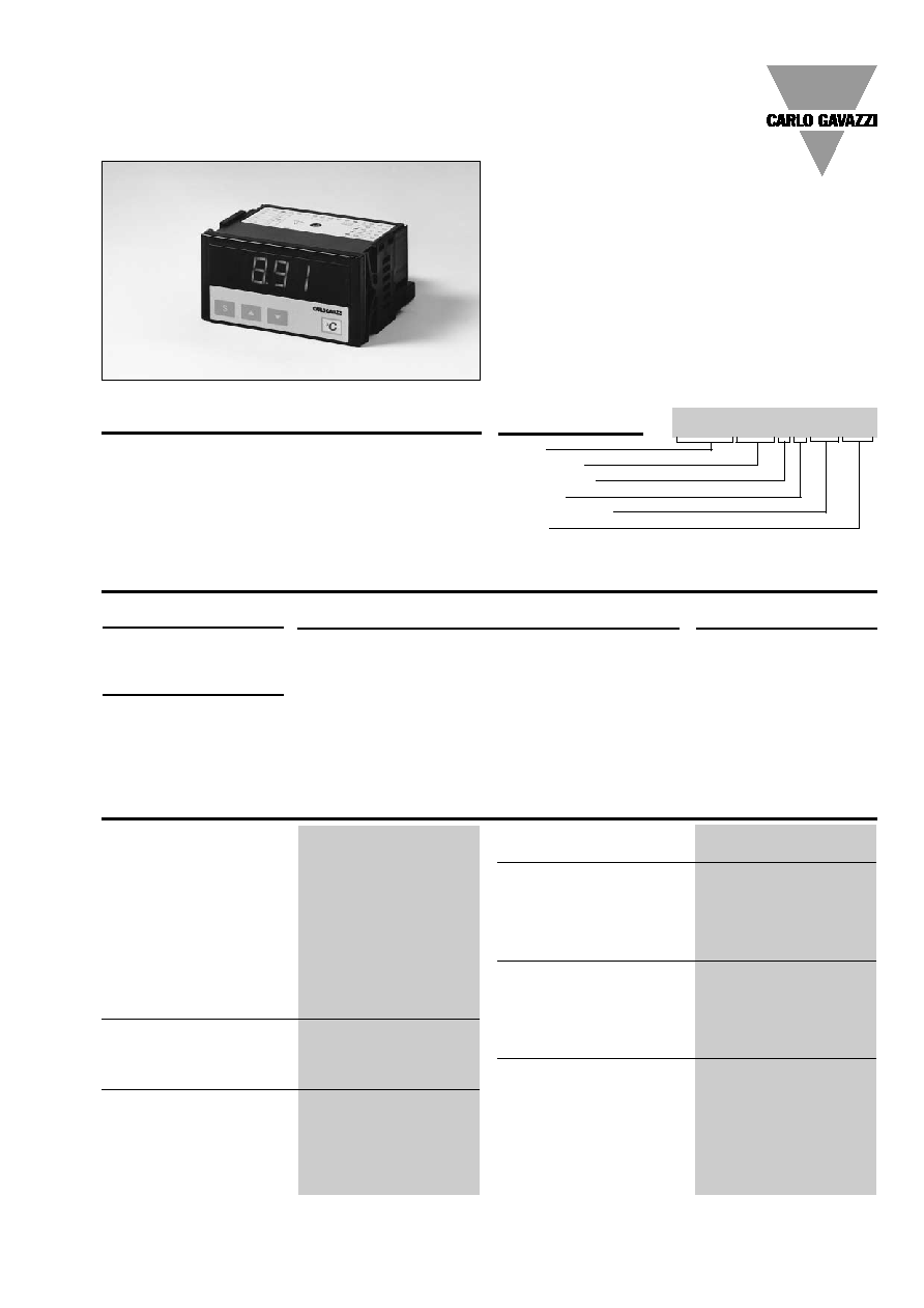
3 1/2-dgt or 3-dgt + dummy
zero multi-range µP-based
indicator or controller for
temperature measurements by
means of thermocouple or
thermoresistance probes. Se-
lectable input range. Degree
of protection of IP 50 (IP 65
on request).
Panel Meters and Controllers
Temperature Meter/Controller
Type LDI35 CF
Type Selection
Power supply
A:
24 VAC, -15% +10%,
50/60 Hz
1)
B:
48 VAC, -15% +10%,
50/60 Hz
1)
C:
115 VAC, -15% +10%,
50/60 Hz
1)
D:
230 VAC, -15% +10%,
50/60 Hz (standard)
E:
120 VAC, -15% +10%,
50/60 Hz
1)
F:
240 VAC, -15% +10%,
50/60 Hz
1)
3:
9 to 32 VDC with
galvanic insulation
1)
6:
40 to 150 VDC with
galvanic insulation
1)
Options
XX:
None (standard)
IX:
Degree of protection
IP 65
AX:
Excitation output
XT:
Tropicalization
Accuracy
RTD
(@ 25∞C ± 5∞C, R.H.
60%)
Pt100/Pt1000
± 0.3 % f.s., ± 2 dgt
Ni100
± 0.5% f.s., ± 2 dgt
TC
(@ 25∞C ± 5∞C, R.H.
60%)
From -5∞C to the limit
of input range
± 0.3% f.s., ± 2 dgt
From -200∞C to -50∞C
of the input range
± 1% f.s., ± 2 dgt
Resistance (@ 25∞C ± 5∞C)
± 0.3 % f.s., ± 2 dgt
Temperature drift
RTD
±200 ppm/∞C
TC
±200 ppm/∞C
Resistance
±200 ppm/∞C
Display
7-segment LED, h 14.2 mm,
3 1/2 digits or
3 digits + dummy zero select-
able by means of the front
key-pad
Sampling rate
2 times/s, dual slope
16 bits A/D converter
Max. and min. indication
RTD/TC
Depending on range and
type of the temperature
probe
Resistance
Max. 200
, min. 0
(2000
on request)
Compensation
RTD/
For 3-wire connections, line
resistance up to 10
.
TC
Cold junction, within the
temperature range from
0 to +50∞C
Key-pad
3 keys:
"S" for menu selection
"UP" and "DOWN" for value
programming/function selec-
tion
Input Specifications
1)
Power supply on request
Range code
See Range Table
Setpoints
0:
No setpoint
1:
1 setpoint
2
Specifications are subject to change without notice
LDI35 CF
Operating temperature
0∞ to 50∞C (32∞ to 122∞F)
(R.H. < 90% non-condensing)
Storage temperature
-10∞ to 60∞C (14∞ to 140∞F)
(R.H. < 90% non-condensing)
Insulation reference voltage
300 V
rms
to ground
Dielectric strength
4000 V
rms
for 1 m inute
Noise rejection
NMRR
40 dB, 40 to 60 Hz
CMRR
100 dB, 40 to 60 Hz
EMC
IEC 60801-2, IEC 60801-3,
IEC 60801-4 (level 3),
EN 50 081-1, EN 50 082-1
Safety standards
EN 61010-1, IEC 61010-1,
VDE 0411
Connector
Screw-type
Housing
Dimensions
1/8 DIN, 48 x 96 x 83 mm
Material
ABS,
self-extinguishing: UL 94 V-0
Degree of protection
IP 50 (IP 65 on request)
Weight
Approx 340 g
Approval
CE, CSA
General Specifications
Password
Numeric code of max. 3 di-
gits; 2 protection levels of
the programming data
1st level:
Password "0", no protection
2nd level:
Password from 1 to 255, all
data are protected
Scaling factor
Operating mode
Electrical scale compression,
compression/expansion of the
displayed scale (max. 2 with-
out digital filter, > 2 with digital
filter)
Electrical scale
Programmable within the
whole measuring range
Decimal point position
Programmable within the
displaying range
Displayed scale
Programmable within the
whole displaying range
Diagnostics
The display flashes when the
limits of the displayed range
are exceeded, the data are
updated up to the maximum
read-out
Burn-out up
TC
Opening of the probe connec-
tion, EEE indication
RTD
Opening of the probe connec-
tion, EEE indication
Probe short-circuit,
-EE indication
Filter
Filter operating range
From 0 to 1999/9990
Filtering coefficient
From 1 to 255
Max. data hold
Automatic storage (RAM only)
of the max. value measured
after the last reset
Software Functions
AC supply
230 VAC, -15% +10%,
50 /60 Hz (standard)
24 VAC, 48 VAC, 115 VAC,
120 VAC, 240 VAC, -15%
+10%, 50/60 Hz (on request)
Insulation
4000 V
rms
supply input to all
other inputs/outputs
DC supply
9 to 32 VDC, G.I.
max. inrush current:
1.2 A/200 ms
40 to 150 VDC, G.I.,
max. inrush current:
0.6 A/200 ms
Insulation
500 V
rms
supply input to all
other inputs/outputs
Power consumption
6.5 VA
Supply Specifications
Excitation output
Voltage
15 VDC non-stabilized/
40 mA max. (on request)
Insulation
100 V
rms
output to
measuring input
4000 V
rms
output to
AC supply input
500 V
rms
output to
DC supply input
Alarms
Number of setpoints
0, (1 on request)
Alarm type
Over-range, up alarm, down
alarm, down alarm with dis-
abling at power-on, up alarm
with latch, down alarm with
latch
Setpoint adjustment
0 to 100% of the displayed
range
Hysteresis
0 to 100% of the displayed
range
On-time delay
0 to 255 s
Off-time delay
0 to 255 s
Relay status
Normally energized/de-ener-
gized
Output type
Contact:
1 x SPDT
Rating:
5A, 250 VAC/VDC 40 W/
1200 VA, 130.000 cycles
Min. response time
500 ms, filter excluded, set-
point on- time delay: "0"
Insulation
2000 V
rms
output to
measuring inputs
2000 V
rms
output to
excitation output
Output Specifications

Specifications are subject to change without notice
3
LDI35 CF
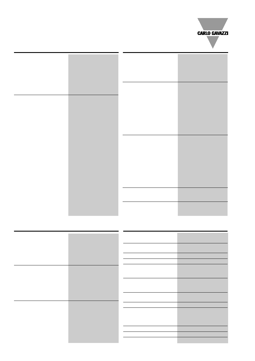
91 mm
75 mm
max. 10
mm
83 mm
92 mm
45 mm
F
96 mm
48 mm
S
Dimensions
Terminal Board
Range code
Input
Probe
Ranges (∫C)
Ranges (∫F)
Other ranges
1)
(3 1/2 dgt)
(3 1/2 dgt)
CFX
RTD
Pt100
-200∞ to 850∞C
-328∞ to 1562∞F
-199.9∞ to +199.9∞C
CFX
RTD
Ni100
-60∞ to 180∞C
-76∞ to 356∞F
-60.0∞ to +180.0∞C
CFP
RTD
Pt1000
-200∞ to 850∞C
-328∞ to 1562∞F
-199.9∞ to +199.9∞C
CFX/CFP
TC
J
-50∞ to 760∞C
-58∞ to 1400∞F
-50.0∞ to +760.0∞C
CFX/CFP
TC
L
-50∞ to 760∞C
-58∞ to 1400∞F
-50.0∞ to +760.0∞C
CFX/CFP
TC
K
-200∞ to 1260∞C
-328∞ to 1999∞F
-199.9∞ to +199.9∞C
CFX/CFP
TC
S
350∞ to 1750∞C
-
-
CFX/CFP
TC
T
-200∞ to 400∞C
-328∞ to 752∞F
-199.9∞ to +199.9∞C
CFX
200.0
0 to 199.9
0∞ to 199.9
0∞ to 19.99
CFP
2000
0 to 1999
0 to 1999
0 to 199.9
1)
Examples of other displayed ranges available by means of the scaling capability
Range Table
S
Front Panel Description
1
2. Display
3 1/2-dgt or 3-dgt + dummy zero
(maximum read-out 1999/9990).
Alphanumeric indication by means of 7-segment display
for:
- Displaying of the measured value, over-range, burn-out
and programming indications.
- Indication of programming parameters.
3. Engineering unit
Screen for interchangeable unit label.The symbols in the
shaded areas are those available on the set of engineering
unit labels supplied with the LDI35 (engineering unit label
to be inserted by customer).
1. Key-pad
Set-up and programming procedures are easily controlled
by the 3 pushbuttons.
"S"
- Selection key to select programming function (instrument
configuration) or measurement and alarm detection.
" " and " "
- Up and down keys for increasing or decreasing program-
ming values.
W = 08
M
= 16
% = 24 mm HG = 32
cm = 40
mV = 01
kW = 09
Hz = 17
mbar = 25
l/min = 33
m = 41
V = 02
MW = 10
kHz = 18
bar = 26
l/h = 34
kg = 42
kV = 03
var = 11
RPM = 19
psi = 27
kg/min = 35
ppm = 43
µA = 04
kvar = 12
m/s = 20
ata = 28
ton/h = 36
kA = 44
mA = 05
Mvar = 13
m/min = 21
ate = 29
m
3
/min = 37
cos
= 45
A = 06
= 14
∞C = 22
kg/cm
2
= 30
m
3
/h = 38
m
3
= 46
mW = 07
k
= 15
∞F = 23 mm H
2
O = 31
mm = 39
µs = 47
2
3