
Specifications are subject to change without notice (12.09.2005)
1
Photoelectrics
Through-beam System, Relay Output
Product Description
Ordering Key
Type
Number of channels
Voltage supply
Output relay
Safety
Adjustable sensitivity
Inverted test input (break)
The MPFRS.. is a family of
inexpensive general purpose
photoelectric sensors in 3 dif-
ferent types of housings with
separate amplifier. They are
designed to meet the require-
ments for industrial doors and
gates. The "Snap-ON" photo
switch can be mounted in
material with a thickness from
0.6 mm and up to 2.25 mm.
The sensor set is easy to use
and no adjustments are nec-
essary. The amplifier has a
test input designed to disable
the emitters and therefore
evaluate the sensor function.
Multiplexed channels prevent
cross-talk between each set
of photosensors. The ampli-
fiers are available with the fol-
lowing voltages: 12-24
VAC/DC, 115 VAC and 230
VAC. The output is made as
positive security e.g. power
lost, short-circuit or broken
sensor cable makes the relay
go to off state.
∑ Industrial doors and gates
∑ Range: 15 m
∑ Modulated infrared light
∑ Option with individually adjustable channel sensitivity
∑ Amplifier with "Snap-ON" photoelectric switches
∑ Supply voltage: 12-24 VAC/DC, 115 VAC or 230 VAC
∑ Output: SPST relay
∑ LED indications for light ON and supply ON
∑ 4 module M36 DIN rail housing
∑ ÿ12 mm "Snap-ON", ÿ18 or M14 photoelectric housing
∑ 1, 2 or 3 multiplexed channels
∑ With make or break test input
∑ UL 325, EN 12453 (TÐV approved)
Type Selection, Amplifier
Housing
Ordering no.
Ordering no.
Ordering no.
W x H x D
Supply: 12-24 VAC/DC
Supply: 115 VAC
Supply: 230 VAC
70 x 57 x 86 mm
MPF1-912 RS
MPF1-115 RS
MPF1-230 RS
MPF2-912 RS
MPF2-115 RS
MPF2-230 RS
MPF3-912 RS
MPF3-115 RS
MPF3-230 RS
MPF1-912 RSI *)
MPF1-115 RSI *)
MPF1-230 RSI *)
MPF2-912 RSI *)
MPF2-115 RSI *)
MPF2-230 RSI *)
MPF3-912 RSI *)
MPF3-115 RSI *)
MPF3-230 RSI *)
MPF1-912 RSA *)
MPF1-115 RSA *)
MPF1-230 RSA *)
MPF2-912 RSA *)
MPF2-115 RSAv
MPF2-230 RSA
MPF3-912 RSA *)
MPF3-115 RSA *)
MPF3-230 RSA *)
MPF1-912 RSAI *)
MPF1-115 RSAI *)
MPF1-230 RSAI *)
MPF2-912 RSAI *)
MPF2-115 RSAI *)
MPF2-230 RSAI *)
MPF3-912 RSAI *)
MPF3-115 RSAI *)
MPF3-230 RSAI *)
*) Products available on request
Type MPF.RS
Type
Emitter
Range
Housing diameter
Optical angle
Connectors on cable
Housing
Rated
Optical
Ordering no.
Ordering no.
Ordering no.
diameter
operational
angle
Emitter
Receiver
Fitting
distance (S
n
)
ÿ12 mm
15 m
4∞
MPFT 15-4
MPFR-4
M14
15 m
4∞
MPFT 15-M14-4
MPFR-M14-4
D18
15 m
4∞
MPFT 15-D18-4
MPFR-D18-4
ÿ12 mm
15 m
4∞
MPFT 15-4C
MPFR-4C
M14
15 m
4∞
MPFT 15-M14-4C
MPFR-M14-4C
D18
15 m
4∞
MPFT 15-D18-4C
MPFR-D18-4C
Fitting for ÿ12
AMPF-MB1
Type Selection, Photoelectric Switch
Sensor
Amplifier
MPF 3 230 RS AI
MPF T 15 M14 4C

2
Specifications are subject to change without notice (12.09.2005)
MPFRS
Rated operation dist. (S
n
)
15 m - 8 m (UL 325)
Light source
LED 880 nm
Light type
Infrared modulated
Ambient light
> 20.000 lux
Housing material
MPFT15-4/C
MPFT15-D18-4/C
MPFR-4/C
MPFR-D18-4/C
Housing
PC
Backpart
ABS
MPFT15-M14-4/C
MPFR15-M14-4/C
Housing
Stainless steel/PC
Backpart
PTE
Connection
MPFT15-XXX-4
MPFR15-XXX-4
Cable
PVC, grey, 10 m, ÿ 2.9 mm
2
Specifications, Photoelectric Switches
Specifications, Amplifier
Output function
MPF1+2
Relay 2 x SPST
MPF3
Relay 2 x SPST + 2 x SPST
Indication function
Supply ON
LED, green
Beam ON (no object present) LED, yellow
Environment
Overvoltage category
III (IEC 66064)
Degree of protection
IP 40 (IEC 60529/60947-5-2)
Pollution degree
3 (IEC 60664/60664A,
60947-1)
Temperature
Operating
-20∞ to +60∞C (-4∞ to +140∞F)
Storage
-30∞ to +80∞C (-22∞ to +176∞F)
Connection
Screw terminals
(max. 2.5 mm
2
)
Protection output
Reverse output, transients,
short-circuit
Test input
MPF.- 230 RS.
Potential-free contact
MPF.- 115 RS.
Potential-free contact
MPF.- 912 RS.
Max. 28 V@15 mA AC/DC
Testfunction activated
3.5 V AC/DC
Testfunction deactivated
1.0 V AC/DC
MPF.- 912 RSI.
Max. 28 V@15 mA AC/DC
Testfunction deactivated
3.5 V AC/DC
Testfunction activated
1.0 V AC/DC
Housing material
PC
Weight
MPF.- 115/230 RS
280 g
MPF.- 912 RS
126 g
CE-marking
Yes
UL-marking
Yes (UL 508, UL 325)
T€V-marking
Yes (EN 12453)
Rated operational volt.
AC types (U
B
)
Terminals 1 & 3
MPF.- 230 RS.
230 VAC ± 15%, 50 to 60 Hz
MPF.- 115 RS.
115 VAC ± 15%, 50 to 60 Hz
MPF.- 912 RS.
12-24 VAC/DC ± 15%, 50 to 60 Hz
Dielectric voltage
MPF.- 230 RS.
4 kVAC (rms)
Rated impulse withstand volt.
4 kV (1.2/50
s)
Rated operational power
MPF.- 912 RS
AC supply
3 VA
DC supply
2 W
MPF.- 115/230 RS
AC supply
max. 4.5 VA
DC supply
max. 4.5 VA
Output Specifications
Resistive load
MPF.-xxx RS, RSA, RSI, RSAI
600.000 switchings
1 A@250 VAC/30 VDC
300.000 switchings
2 A@250 VAC/30 VDC
100.000 switchings
2 A@250 VAC/30 VDC (UL)
AC15
0.75 A@240 VAC
AC14
0.60 A@120 VAC
DC13
0.22 A@125 VDC
Rated insulation volt. (U
i
)
MPF.- 230 RS.
250 VAC (rms)
MPF.- 115 RS.
120 VAC (rms)
MPF.- 912 RS.
50 VAC (rms), 50 VDC
Operating frequency (f)
Light/dark ratio 1:1
Contact output
10 Hz
Response time
OFF-ON (t
ON
)
50 ms
ON-OFF (t
OFF
)
40 ms
Power ON delay (t
v
)
300 ms
MPFT15-XXX-4C
Red connector pair
MPFR15-XXX-4C
White connector pair
Connector is placed 15 cm from sensorhead
Cable
PVC, grey, 10 m, ÿ 2.9 mm
2
Degree of protection
IP 67 (IEC 60529/60947-5-2)
Mounting
"Snap-ON"
ÿ12 mm or fitting
MPFT15-4/C
MPFR-4/C
Rubber profile
D18
MPFT15-D18-4/C
MPFR-D18-4/C
Threaded barrel
M14
MPFT15-M14-4/C
MPFR-M14-4/C
CE-marking
Yes
UL-marking
Yes (UL 508, UL 325)
T€V-marking
Yes (EN 12453)
Specifications are subject to change without notice (12.09.2005)
3
Tv
Toff
Ton
Ton
Operation Diagram
Output contact closed
Object present
Power supply
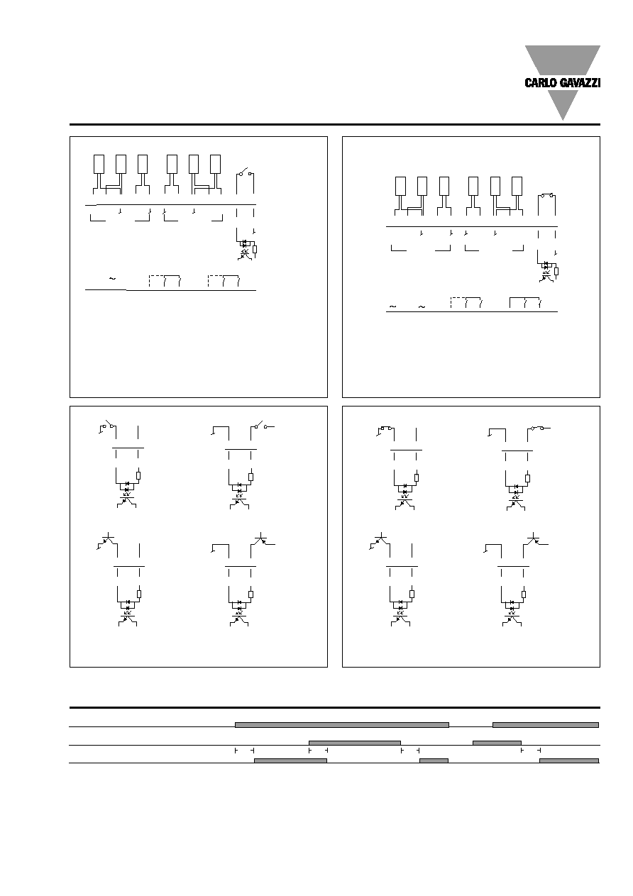
Wiring Diagrams
MPFRS
EMITTER
OUT 3
OUT 1+2
TEST
RECEIVER
3
1
2
2
1
3
SUPPLY
230 V
13 14 15 16 17 18 19 20 21 22 23 24
1 2 3 4 5 6 7 8 9
10
11
12
TX3
TX2
TX1
RX1
RX2
RX3
+
-
+
TP
TP
250 VAC
30 VDC
Max. 2 A
TEST
23 24
AC/DC
TEST
23 24
AC/DC
TEST
23 24
DC
TEST
23 24
DC
Test input make, shown for 912 version
Test input make, shown for 115/230 version
OUT 3
TEST
3
1
2
2
1
3
13 14 15 16 17 18 19 20 21 22 23 24
1 2 3 4 5 6 7 8 9
10
11
12
TX3
TX2
TX1
RX1
RX2
RX3
+
TP
TP
250 VAC
30 VDC
Max. 2 A
1)
2)
2)
1)
EMITTER
RECEIVER
RD RD BK RD BK BK BU BK BU BU
SUPPLY
115/230 V
OUT 2
1
Test input break, shown for 115/230 version
TEST
23 24
DC
TEST
23 24
DC
Test input break, shown for 912 version
1) Not MPF1 and MPF2
2) Not MPF1
1) Not MPF1 and MPF2
2) Not MPF1
TEST
23 24
AC/DC
TEST
23 24
AC/DC

4
Specifications are subject to change without notice (12.09.2005)
MPFRS
Excess Gain
1
10
100
1000
1000
10000
100000
Range [mm]
Excess gain
Detection Diagram
60
40
20
0
-20
-40
-60
0 4 8 12 16 20
Sensing Range (m)
(cm)
0
9.5 26.2 39.4 52.5 65.6
(feet)
23.8
15.7
7.9
0
-7.9
-15.7
-23.8
(inch)
Y
X
Emitter
Receiver
Dimensions
57
70
48
86
MPF3-230RS
PHOTOELECTRIC
EMITTER
OUT 3 250 VAC
30 VDC
MAX 2A
OUT 1+2
TEST
RECEIVER
AMPLIFIER
3
1
2
2
1
3
CH1
CH2
CH3
SUPPLY
230 V
ÿ15
ÿ2.9
ÿ11.8
17.3
2.6
0.6 - 2.25 mm
ÿ12
ÿ2.9
ÿ10
5
20
2.6
M14 x 1
27.6
ÿ12.8
ÿ2.9
ÿ17.5
ÿ22
8.1
R6
ÿ6
28.3
5
19
24
33.2
ÿ12
M14
D18
Fitting for ÿ12
Amplifier
To be mounted in material with a thickness of 0.6 - 2.25 mm
Max. Rating
------ Potentiometer in min.

Specifications are subject to change without notice (12.09.2005)
5
Delivery Contents
∑ Amplifier, MPF..
∑ Installation instruction
∑ Packaging: cardboard box
Installation Hints
Relief of cable strain
Protection of the sensing face
Switch mounted on mobile carrier
To avoid interference from inductive voltage/
current peaks, separate the prox. switch pow-
er cables from any other power cables, e.g.
motor, contactor or solenoid cables
Incorrect
Correct
The cable should not be pulled
A proximity switch should not serve as
mechanical stop
Any repetitive flexing of the
cable should be avoided