 | –≠–ª–µ–∫—Ç—Ä–æ–Ω–Ω—ã–π –∫–æ–º–ø–æ–Ω–µ–Ω—Ç: RP1B40D3 | –°–∫–∞—á–∞—Ç—å:  PDF PDF  ZIP ZIP |
Specifications are subject to change without notice (02.10.2003)
1
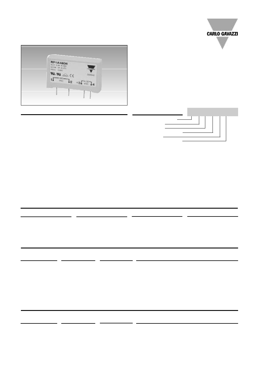
Solid State Relays
PCB, 1-Phase ZS/IO
Type RP1A, RP1B
∑ AC Solid State Relay for PCB mounting
∑ Zero switching or instant-on
∑ Rated operational current: 3, 5 or 5.5 A
∑ Rated operational voltage: Up to 480 V
∑ Surface mount technology
∑ Flexible encapsulation for extended life
∑ Control voltage: 3 to 32 VDC* /
16
to 32 VAC**
∑ Opto-isolation: > 4000 VACrms
∑ Non-repetitive peak voltage: 1000 Vp
∑ Non-repetitive surge current up to 300 A
Product Description
Ordering Key
Solid State Relay (PCB)
Number of poles
Switching mode
Rated operational voltage
Control voltage
Rated operational current
Rated operational
Non-rep. voltage
Control voltage
Rated operational current
voltage
3 AACrms
5 AACrms
5.5 AACrms
230 VACrms
650 Vp
3 to 32 VDC
RP1A23D3
RP1A23D5
RP1A23D6
RP1B23D3
RP1B23D5
RP1B23D6
16
to 32 VAC
RP1A23A6
400 VACrms
850 Vp
3 to 32 VDC
RP1A40D3
RP1A40D5
RP1A40D6
RP1B40D3
RP1B40D5
RP1B40D6
480 VACrms
1000 Vp
4 to 32 VDC
RP1A48D3
RP1A48D5
RP1A48D6
RP1B48D3
RP1B48D5
RP1B48D6
Switching mode
Rated operational voltage
Rated operational current
Control voltage
A: Zero switching
23: 230 V
3: 3 A
D:
3 to 32 VDC*
B: Instant-On switching
40: 400 V
5: 5 A
A:
16
to 32 VAC**
48: 480 V
6: 5.5 A
* 4 to 32 VDC for 480 VAC types
** Only available for 230V, 5.5 A
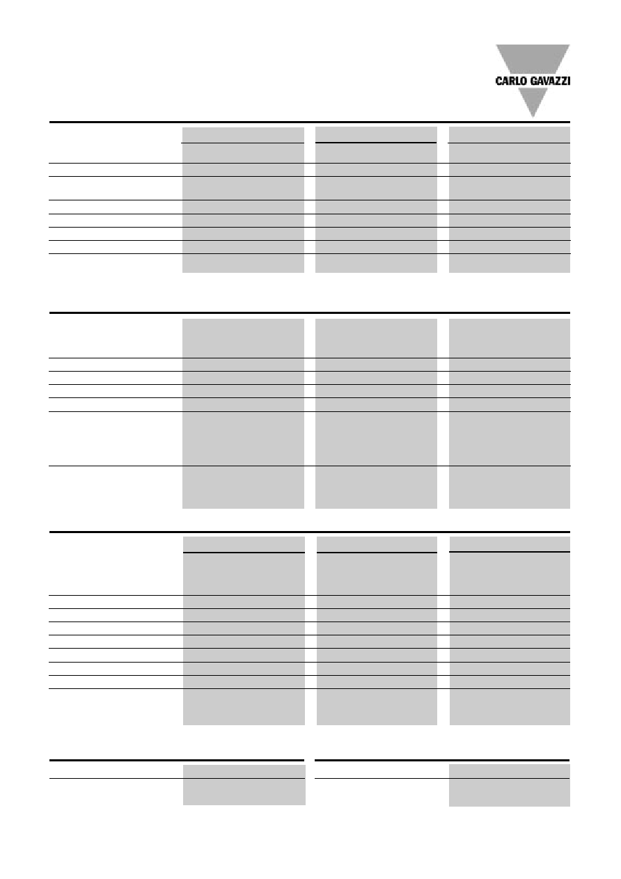
Type Selection
Selection Guide
RP 1 A 23 D 3
The RP1 is an SSR series for
socket- or PCB-mounting,
providing an ideal interface
between logic controls and
AC loads. The RP1 is
designed for resistive and
inductive loads up to 480V.
Two regulated control voltages
cover most standard input
requirements in an economic
package. These features
allow a direct substitution of
existing PCB mounted relays
with RP1. Internally this new
series enjoys an improved
technical design with the intro-
duction of stress-free flexible
encapsulation and automated
assembly of components.
Opto-isolation and load
switching are performed by
individual components, pro-
viding higher reliability than
monolithic designs. Addition-
ally RP1..6 is a special version
with high current surge capa-
bility that reduces fusing
requirements. This relay can
also drive higher AC3 loads up
to 5 A. The Solid State tech-
nology used can withstand
peak voltages of 1000V, mak-
ing the RP1 series suitable to
drive AC loads such as valve
solenoids and small induction
motors.
Rated operational
Non-rep. voltage
Control voltage
Rated operational current
voltage
3 AACrms 5 AACrms
5.5 AACrms
230 VACrms
650 Vp
4 to 32 VDC
RP1A23D3M1
RP1A23D5M1
RP1A23D6M1
RP1B23D3M1
RP1B23D5M1
RP1B23D6M1
16 to 32 VAC
RP1A23A6M1
Selection Guide (mounted on DIN EN adaptor)
2
Specifications are subject to change without notice (02.10.2003)
Insulation Input - Output
Insulation resistance
10
10
Insulation capacitance
8 pF
RP 1
RP1....3
RP1....5
RP1....6
Rated operational current
AC 51 @ T
a
= 25∫C
3 A
5 A
5.5 A
AC 53a @ T
a
= 25∫C
2 A
3 A
5 A
Min. operational load current
20 mA
20 mA
20 mA
Rep. overload current t=1 s
10 A
p
12 A
p
16 A
p
Non-rep. surge current t=20 ms 65 A
p
80 A
p
300 A
p
Off-state leakage current
< 1 mA
< 1 mA
< 1 mA
I
2
t for fusing t=10 ms
20 A
2
s
50 A
2
s
400 A
2
s
Critical dI/dt @ 50 Hz
50 A/µs
20 A/µs
20 A/µs
Critical dV/dt off state min.
250 V/µs
500 V/µs
500 V/µs
On-state voltage drop
@ rated current
< 1.2 Vrms
< 1.2 Vrms
< 1.2 Vrms
Output Specifications
Operating temperature
-20∞ to +70∞C (-4∞ to +158∞F)
Storage temperature
-40∞ to +100∞C (-40∞ to +212∞F)
Thermal Specifications
RP1..23D..
RP1..48D..
RP1..23A6..
RP1..40D..
Control voltage
3 - 32 VDC
4 - 32 VDC
16
- 32 VAC
Pick-up voltage
2.5 VDC
3.5 VDC
10 VAC
Drop-out voltage
1.2 VDC
1.2 VDC
5 VAC
Input current max.
10 mADC
10 mADC
13 mAAC
Max. reverse voltage
32 VDC
32 VDC
-
Response time pick-up
RP1A
< 10 ms
< 10 ms
< 20 ms
RP1B
12 VDC/50 Hz
< 160 µs
< 160 µs
-
5 VDC/50 Hz
< 320 µs
< 320 µs
-
Response time drop-out
RP1A
< 10 ms
< 10 ms
< 20 ms
RP1B
< 10 ms
< 10 ms
-
Input Specifications
RP1.23..
RP1.40..
RP1.48..
Operational voltage range
12 - 265 VACrms
12 - 440 VACrms
12 - 530 VACrms
Non-rep. peak voltage
650 V
p
850 V
p
1000 V
p
Rated insulated input to output
out to heatsink
4 kVACrms
4 kVACrms
4 kVACrms
Operational frequency range
45 - 65 Hz
45 - 65 Hz
45 - 65 Hz
Power factor
> 0.5
> 0.5
> 0.5
Zero voltage turn-on
< 10 V
< 10 V
< 10 V
Approvals
UL, cUL, VDE*
UL, cUL, VDE*
UL, cUL, VDE*
CE-marking
Yes
Yes
Yes
* VDE 0700, VDE 0805
General Specifications
Specifications are subject to change without notice (02.10.2003)
3
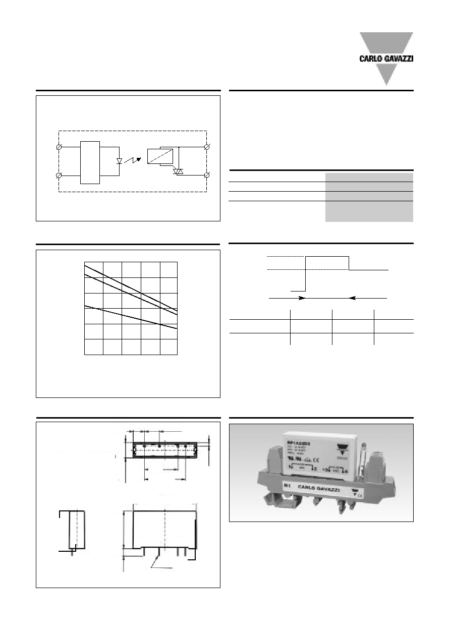
Increased Current Options
Dimensions
RP 1
I peak (Amps)
6
8
10
D5 : t (minutes)
15
5
3
D6 : t (minutes
15
5
3
t
T
amb
= 25∞C
I
peak
I
nom
Note: Even though the D3 can withstand a slight increase
in current for a limited time, it is not recommended for
this purpose.
These relays can be used to switch heaters, motors, lights,
valves or solenoids.
When used at full load current, the relays must be placed
vertically. If more than one relay is mounted, please allow a
minimum distance of 20 mm in between for sufficient air
cooling.
Applications
M = 1/10" = 2.54mm
* = +/- 0.2mm
** = +/- 0.5mm
3M
43 *
10.5 **
9M
11M
1 2
+3 4
4 x ¯1
6 **
25.4 *
0.5 **
1M
1(~)
2(~)
3
4
REGULA
TION
ZC
IO
Functional Diagram
Control
input
Accessories
M1 DIN-rail adaptor (photo)
Varistors
Fuses
For further information refer to "General Accessories".
Derating Curve
Derating curve is used for finding max. load current at an elevated ambi-
ent temperature. The 3 lines in the graph represent the 3 nominal current
ratings of the RP1 series (RP1...D3/D5/D6).
4
6
5
3
2
1
0
20 30
40
50
60 70
D6
D5
D3
Housing Specifications
Weight
Approx. 20 g
Housing material
PBT, grey
Terminals
Copper alloy, tin-plated
Potting compound
Flame-retardant flexible
silicone rubber
(~)
(+)
3
(~)
(-)
4
2
1
4M