Specifications are subject to change without notice (30.09.2005)
1
Control voltage
HD: 10 - 40 VDC
LA: 90 - 140 VAC
HA: 180 - 265 VAC
Rated operational
voltage
40: 400 VACrms
48: 480 VACrms
Interlocking
I: Interlock
This family of motor reversing
Solid State Relays is designed
to switch 3-phase motors rat-
ed up to 3 kW. The built-in in-
terlocking circuitry for both AC
and DC control voltage pre-
vents the relay from switching
both directions at the same
time. A dual colour LED indi-
cates direction "forward"
when green and direction "re-
verse" when red. The output
alternistor chips are protected
from excessive voltage fluctu-
ations (transients) by the
built-in varistors. Further-
more, optimum reliability is
achieved by soldering the
output alternistor chips direct-
ly on to the ceramic substrate
(Direct Copper Bonding).
The housing is designed to
incorporate a temperature
limit switch. It is recommend-
ed to install an appropriate
semiconductor fuse in series
with the relay.
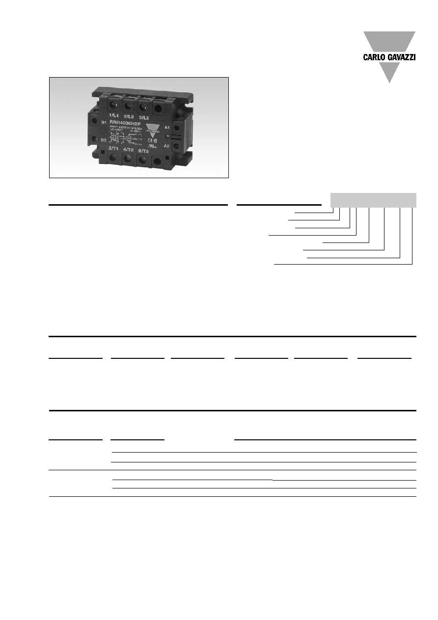
Motor Controllers
Industrial, 2-Phase IO Reversing
Types RR2 I .... HAP, RR2 I .... LAP, RR2 I .... HDP
Ordering Key
Product Description
Solid State Relay
Reversing type
Switched phases
Interlock
Rated operational voltage
Motor power rating
Input control voltage
Protection
∑
Motor reversing Solid State Relays
for 3-phase induction motors up to 3 kW
∑
Rated operational voltage: Up to 480 VACrms
∑
Built-in interlock function
∑
AC or DC control voltage
∑
Built-in voltage transient protection
∑
LED indication for direction
∑
Insulation: Reed relay or optocoupler (input-output)
4000 VACrms
∑
Direct copper bonding technology
Protection
P: Protected
(varistor)
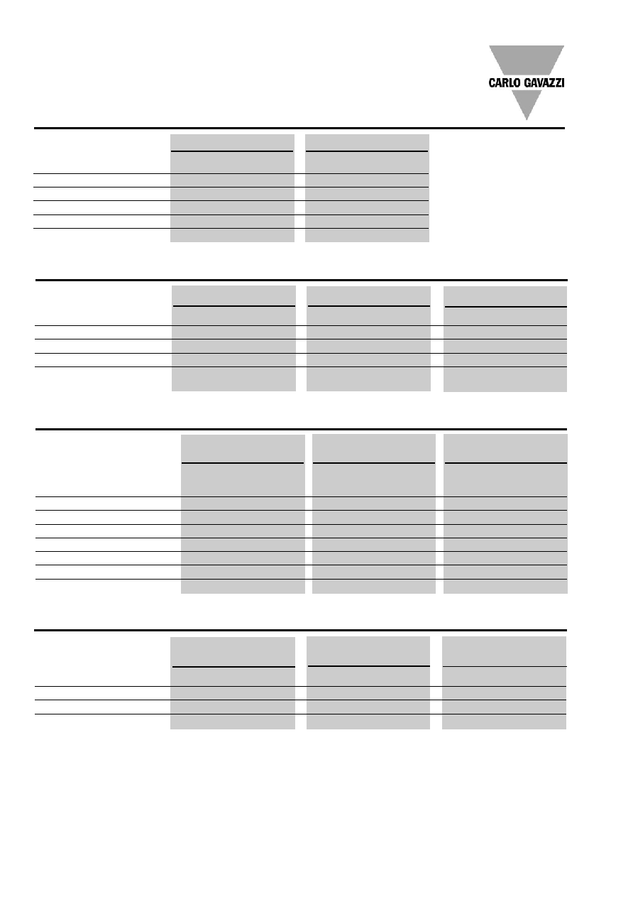
10 to 40 VDC
RR2 I 4005 HDP
RR2 I 4015 HDP
RR2 I 4030 HDP
90 to 140 VAC
RR2 I 4005 LAP
RR2 I 4015 LAP
RR2 I 4030 LAP
180 to 265 VAC
RR2 I 4005 HAP
RR2 I 4015 HAP
RR2 I 4030 HAP
10 to 40 VDC
RR2 I 4805 HDP
RR2 I 4815 HDP
RR2 I 4830 HDP
90 to 140 VAC
RR2 I 4805 LAP
RR2 I 4815 LAP
RR2 I 4830 LAP
180 to 265 VAC
RR2 I 4805 HAP
RR2 I 4815 HAP
RR2 I 4830 HAP
Load power
05: 0.5 kW
15: 1.5 kW
30: 3.0 kW
Type Selection
Switching mode
RR2: Reversing re-
lay (2-phase)
Selection Guide
Control
voltage
400 VACrms
Rated opera-
tional voltage
Load power
0.5 kW
1.5 kW
3.0 kW
480 VACrms
RR 2 I 40 05 HD P
2
Specifications are subject to change without notice (30.09.2005)
RR2 I .... HAP, RR2 I .... LAP, RR2 I .... HDP
Input Specifications
RR2 I 4005 ..P
RR2 I 4015 ..P
RR2 I 4030 ..P
RR2 I 4805 ..P
RR2 I 4815 ..P
RR2 I 4830 ..P
Rated operational current AC51
2 x 10 AACrms
2 x 25 AACrms
2 x 40 AACrms
AC53a
2 x 1.5 AACrms
2 x 3.5 AACrms
2 x 6 AACrms
Min. operational current
200 mArms
200 mArms
200 mArms
Off-state leakage current
10 mA
10 mA
10 mA
I
2
t for fusing t=1-10 ms
72 A
2
s
450 A
2
s
760 A
2
s
Critical dI/dt
50 A/µs
50 A/µs
50 A/µs
On-state voltage drop
1.6 V rms
1.6 V rms
1.6 V rms
Critical dV/dt commutating
200 V/µs
200 V/µs
200 V/µs
Critical dV/dt off-state
500 V/µs
500 V/µs
500 V/µs
Output Specifications
RR2 I .... HDP
RR2 I .... LAP
RR2 I .... HAP
Control voltage range
10 to 40 VDC
90 to 140 VAC
180 to 265 VAC
Pick-up voltage
10 VDC
90 VAC
180 VAC
Drop-out voltage
3 VDC
30 VAC
60 VAC
Power consumption
1.4 W
4 VA
4 VA
Time delay
F
R, R
F
50 ms
100 ms
100 ms
General Specifications
RR2 I 40.. ..P
RR2 I 48.. ..P
Operational voltage range
120 to 440 VACrms
120 to 530 VACrms
Non-rep. peak voltage
1200 V
p
1400 V
p
Operational frequency range
45 to 65 Hz
45 to 65 Hz
Power factor
0.5 @ 400 VACrms
0.5 @ 480 VACrms
Approvals
CSA, UL, cUL
CSA, UL, cUL
CE-marking
Yes
Yes
Thermal Specifications
RR2 I 4005 ..P
RR2 I 4015 ..P
RR2 I 4030 ..P
RR2 I 4805 ..P
RR2 I 4815 ..P
RR2 I 4830 ..P
Operating temperature
-20∞ to +70∞C (-4∞ to +158∞F)
-20∞ to +70∞C (-4∞ to +158∞F)
-20∞ to +70∞C (-4∞ to +158∞F)
Storage temperature
-40∞ to +100∞C (-40∞ to 212∞F)
-40∞ to +100∞C (-40∞ to 212∞F)
-40∞ to +100∞C (-40∞ to 212∞F)
Junction temperature
125∞C (257∞F)
125∞C (257∞F)
125∞C (257∞F)
R
th
junction to case
2.3 K/W
1.5 K/W
0.8 K/W
Specifications are subject to change without notice (30.09.2005)
3
RR2 I .. .. HAP, RR2 I .... LAP, RR2 I .... HDP
Insulation
Rated insulation voltage
Input to output
4000 VACrms
Input to case
4000 VACrms
Rated insulation voltage
Output to case
4000 VACrms
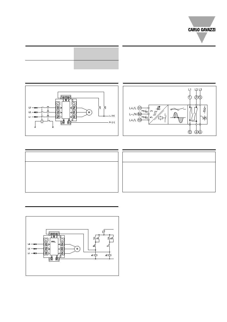
Wiring Diagram
F3
F1
F2
Pilot
voltage
3
R
F
Functional Diagram
Control
inputs
Mains
inputs
Load
outputs
Applications
AC/DC input forward/reverse/stop
3
Stop
F
AC/DC
CON
Heatsink Dimensions
Fuse Selection Guide
Relay
Fuse
FERRAZ PROTISTOR
RR2 I 4005 ..P
660 g RB 10-10
RR2 I 4015 ..P
660 g RB 10-25
RR2 I 4030 ..P
6.621 CP URGB 14 x 51/40
RR2 I 4805 ..P
660 g RB 10-10
RR2 I 4815 ..P
660 g RB 10-25
RR2 I 4830 ..P
6.621 CP URGA 22 x 58
R
Motor
Relay
Type of heatsink
load
(at max. 50
∞
C ambient temp.)
0.5 kW
RR2 I 4.05 ..P
No heatsink required
(mounted on backplate)
1.5 kW
RR2 I 4.15 ..P
2.5 K/W
3.0 kW
RR2 I 4.30 ..P
1.0 K/W
Accessories
Heatsinks
For further information refer
Fuses
to "General Accessories".
Temperature limit switch
4
Specifications are subject to change without notice (30.09.2005)
RR2 I .... HAP, RR2 I .... LAP, RR2 I .... HDP
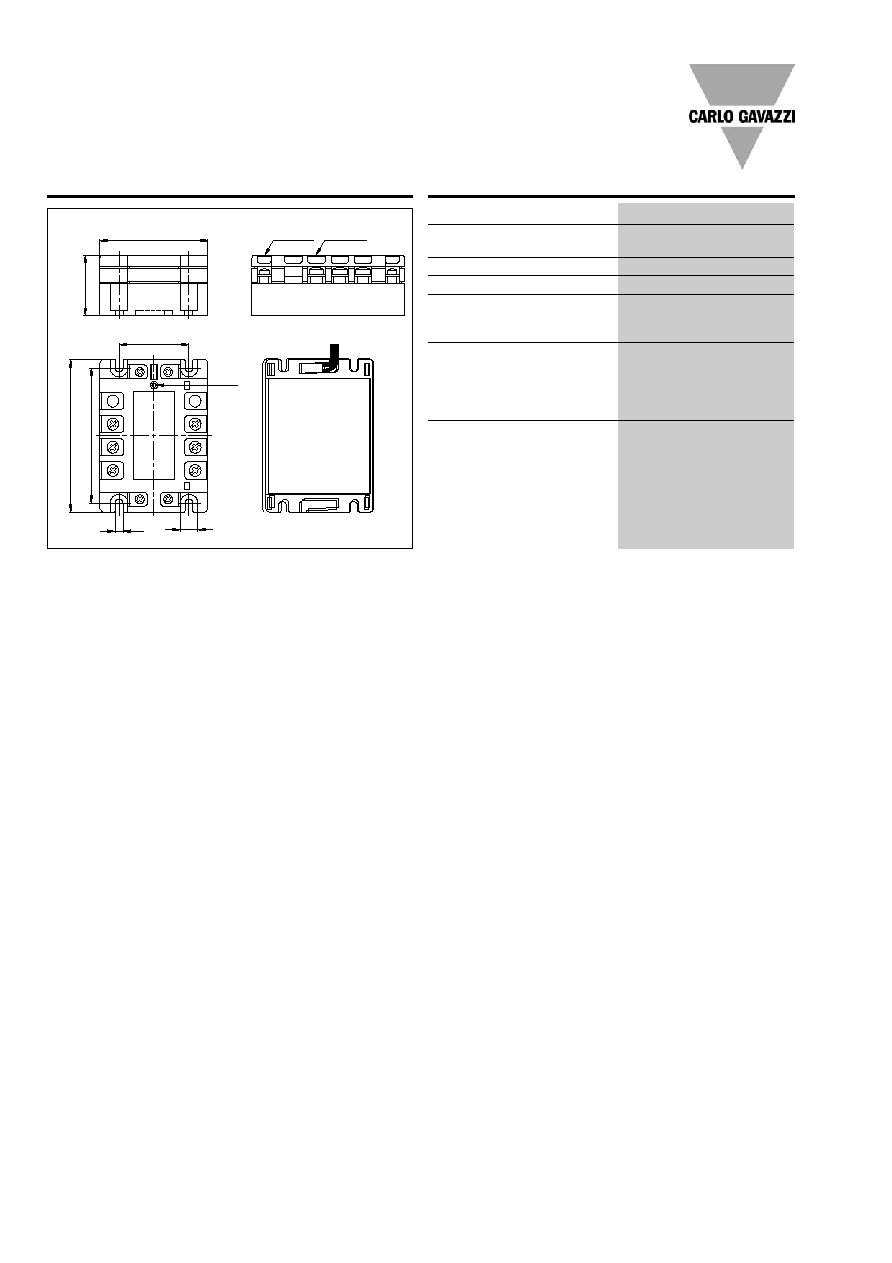
Housing Specifications
Weight
Approx. 350 g
Housing material
Noryl, glass-reinforced
Colour
Black
Base plate
Aluminium, nickel-plated
Potting compound
Polyurethane, black
Relay
Mounting screws
M5
Mounting torque
1.5 Nm
Control terminal
Mounting screws
M4
Mounting torque
0.5 Nm
Wire size
Max.
2 x 2.5 mm
2
(AWG 14)
Min.
2 x 1.0 mm
2
Power terminal
Mounting screws
M5
Mounting torque
2.5 Nm
Wire size
Max.
2 x 6 mm
2
(AWG 8)
Min.
2 x 1 mm
2
Dimensions
73.5
47.6
4 x M4 6 x M5
LED
12
5.3
41
103
92
Use heatsink
compound
All dimensions in mm