
Specifications are subject to change without notice
(30.09.2005)
1
Type
Rated operational
Rated operational
Control voltage
voltage U
e
current I
e
U
c
*)
RSE: E-series,
22: 127/220 VACrms, 50/60 Hz 03: 3 A
-B: 24 to 110 VAC/DC
motor controller
40: 230/400 VACrms, 50/60 Hz 12: 12 A
& 110 to 480 VAC
48: 277/480 VACrms, 50/60 Hz
60: 346/600 VACrms, 50/60 Hz
*) The control voltage should never be higher than the rated operational voltage.
Solid State Relay
Motor controller
E-line housing
Rated operational voltage
Rated operational current
Control voltage
Ordering Key
Motor Controllers
AC Semiconductor Motor Controller
Types RSE 22 .. - B, RSE 4. .. - B, RSE 60 .. - B
RSE 40 03 - B
�
Soft starting and stopping of 3-phase
squirrel cage motors
�
Rated operational voltage: Up to 600 VACrms, 50/60 Hz
�
Rated operational current: 3 A or 12 AAC 53 b
�
Potential-free control input
�
LED-indications for supply and operation
�
Transient overvoltage protection built-in
� Integral bypassing of semiconductors
Product Description
Compact easy-to-use AC
semiconductor motor con-
troller. With this controller 3-
phase motors with nominal
load currents up to 12 A can
be soft-started and/or soft-
Type Selection
stopped. Starting and stop-
ping time as well as initial
torque can be independently
adjusted by built-in potentio-
meters.
Input Specifications (Control Input)
Control voltage U
c
A1-A2:
24 - 110 VAC/DC �15%,
12 mA
A1-A3:
110 - 480 VAC �15%,
5 mA
Rated insulation voltage
630 V rms
Overvoltage cat. III (IEC 60664)
Dielectric strength
Dielectric voltage
2 kVAC (rms)
Rated impulse withstand volt. 4 kV (1.2/50 �s)
Output Specifications
Utilization category
AC-53b Integral bypassing
of semiconductors
Overload current profile
(overload relay trip class)
RSE ..03-B
3A: AC-53b:3-5:30
RSE ..12-B
12A: AC-53b:3-5: 180
Min. load current
RSE ..03-B
100 mAAC rms
RSE ..12-B
200 mAAC rms
2
Specifications are subject to change without notice
(30.09.2005)
M
3~
RSE 22 .. - B, RSE 4. .. - B, RSE 60 .. - B
Power supply
Overvoltage cat. III (IEC 60664)
Rated operational volt. (U
e
)
through terminals L1-L2-L3
(IEC 60038)
22
127/220 VAC rms �15%
50/60 Hz -5/+5 Hz
40
230/400 VAC rms �15%
50/60 Hz -5/+5 Hz
48
277/480 VAC rms �15%
50/60 Hz -5/+5 Hz
60
346/600 VAC rms �15%
50/60 Hz -5/+5 Hz
Voltage interruption
40 ms
Dielectric voltage
None
Rated impulse withstand volt. 4 kV (1.2/50 �s)
Rated operational power
2 VA
supplied from
L1-L3
Accuracy
Ramp up
5.5 - 7.5 s on max.
0.5 s on min.
Ramp down
6 - 10 s on max.
0.5 s on min.
Initial torque
70 - 100% on max.
5% on min.
EMC
Electromagnetic Compatibility
Immunity
acc. to EN 61000-6-2
Indication for
Power supply ON
LED, green
Ramp up/down bypassing relay LED, yellow
Environment
Degree of protection
IP 20
Pollution degree
3
Operating temperature
-20� to +50�C (-4� to +122�F)
Storage temperature
-50� to +85�C (-58� to +185�F)
Screw terminals
Tightening torque
Max. 0.5 Nm acc. to IEC 60947
Terminal capacity
2 x 2.5 mm
2
Approvals
CSA (<7.5 HP @ 600 VAC),UL, cUL
CE-marking
Yes
Mode of Operation
Rated opera-
I
2
t for fusing
I
TSM
dI/dt
tional current
t = 1 - 10 ms
3 A
72 A
2
s
120 A
p
50 A/�s
12 A
610 A
2
s
350 A
p
50 A/�s
Semiconductor Data
This motor controller is in-
tended to be used to softstart/
softstop 3-phase squirrel cage
induction motors and thereby
reduce the stress or wear on
gear and belt/chain drives and
to give smooth operation of
machines. Soft starting and/or
stopping is achieved by con-
trolling the motor voltage.
During running operation the
semiconductor is bypassed by
an internal electromechanical
relay.
The initial torque can be ad-
justed from 0 to 85% of the
nominal torque.
The soft-start and soft-stop
time can be adjusted from 0.5
to approx. 7s.
A green LED indicates supply.
Two yellow LEDs indicate
Ramp up/down and Running
mode.
Overload protection is not pro-
vided in this motor controller
and must therefore be in-
stalled separately.
The controller is switching
2 lines. The 3rd line is continu-
ously connected to the load.
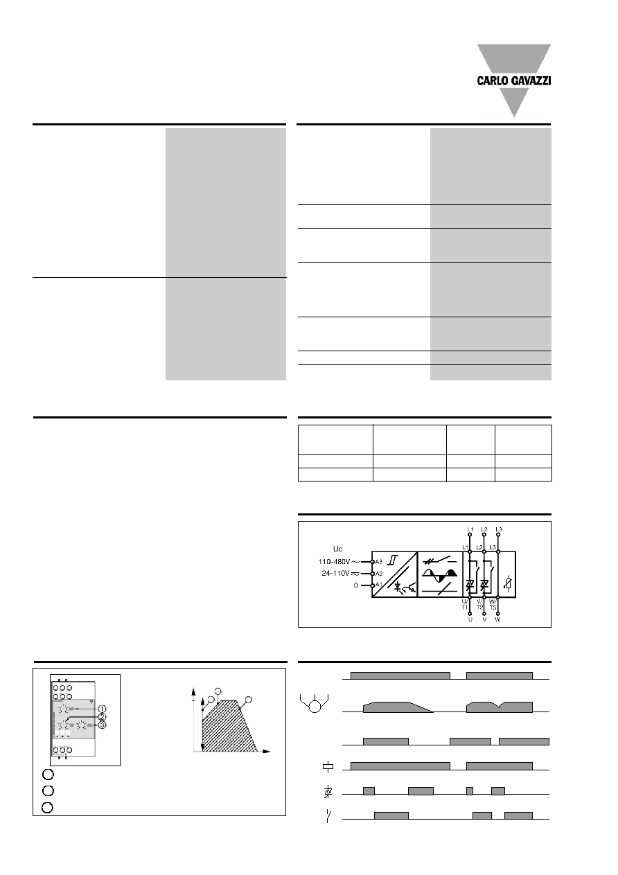
Functional Diagram
Operation Diagram 2
Operation Diagram 1
Time
Motor voltage
100%
1
Ramp-up time 0.5 to 6.5s. Time from zero load voltage to full load
voltage.
Ramp-down time 0.5 to 8.0s. Time from full load voltage to zero
load current.
Initial torque 0 to 85% voltage at the start of the ramp-up function.
2
3
1
2
3
Mains Ue
Control input Uc
LED
LED
LED
Supply Specifications
General Specifications
Specifications are subject to change without notice
(30.09.2005)
3
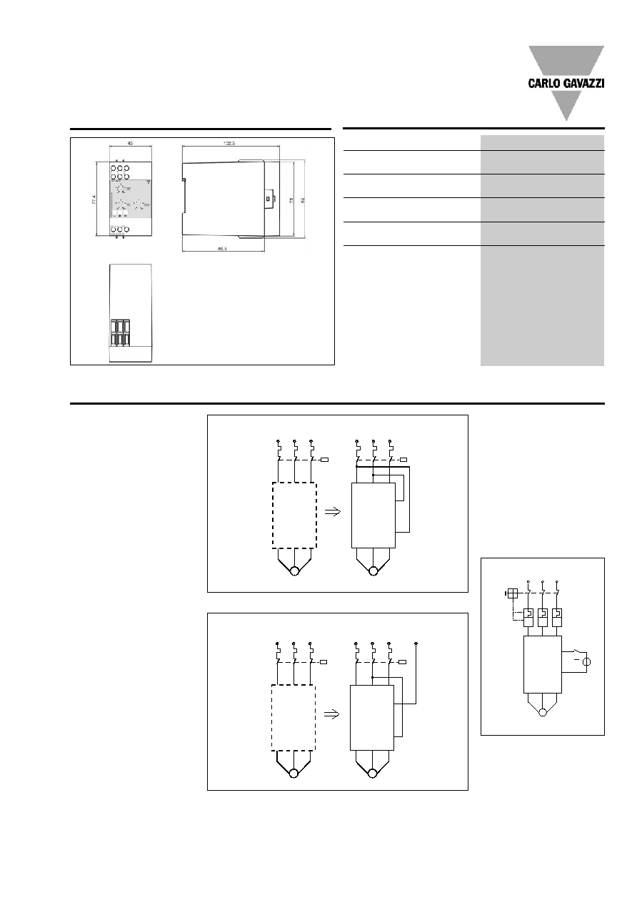
Dimensions
Weight
270 g
Housing material
PC/ABS Blend
Colour
Light grey
Terminal block
PBTP
Colour
Ligh grey
Bottom clip
POM
Colour
Black
Diode cover
PC
Colour
Grey Transparent
Front knob
PA
Colour
Grey
Housing Specifications
Applications
RSE 22 .. - B, RSE 4. .. - B, RSE 60 .. - B
Changing from Direct ON
Line start to soft start
(Line controlled soft-start)
(Fig. 1 & Fig. 2)
Changing a Direct On Line start
into a soft start is very simple
with the RSE soft-starting re-
lay:
1) Cut the cable to the motor
and insert the RSE relay.
2) Connect control input to two
of the incoming lines. Set
initial torque to minimum and
ramp up and down to maxi-
mum.
3) Power up again - adjust the
start torque so the motor
starts turning immediately
after power is applied, and
adjust ramp time to the
appropriate value.
When C1 is operated, the
motor controller will perform
soft-start of the motor. When
C1 is switched off, the motor
will stop, the motor controller
will reset and after 0.5 s a new
soft-start can be performed.
Please note that the controller
does not insulate the motor
from the mains. Contactor C1
is therefore needed as a ser-
vice switch for the motor.
Fig. 1
Fig. 2 For voltages higher than 480 VAC
Soft-start and soft-stop
(Fig. 3)
When S1 is closed, soft-start
of the motor will be performed
according to the setting of the
ramp-up potentiometer and
the setting of the initial torque
potentiometer. When S1 is
opened, soft-stop will be per-
formed according to the set-
ting of the ramp-down
potentiometer.
1L1 3L2 5L3
L1 L2 L3
A1
A2
A3
U/T1 U/T2 W/T3
M
Fig. 3
S1
I >
I >
I >
~
L1 L2 L3
L1 L2 L3
C1
C1
L1 L2 L3
L1 L2 L3
M
M
U/T1 U/T2 W/T3
U/T1 U/T2 W/T3
A1
A2
A3
L1 L2 L3
L1 L2 L3
N
L1 L2 L3
L1 L2 L3
M
M
U/T1 U/T2 W/T3
U/T1 U/T2 W/T3
A2
A3
A1
All dimensions in mm
4
Specifications are subject to change without notice
(30.09.2005)
RSE 22 .. - B, RSE 4. .. - B, RSE 60 .. - B
Time between rampings
To prevent the semiconduc-
tors from overheating, a cer-
tain time between ramping
should be allowed. The time
between rampings depends
on the motor current during
ramping and ramp time (see
tables below).
Fusing Considerations
The motor controller provides
by-passing of the semicon-
ductors during running opera-
tion. Therefore the semicon-
ductors can only be damaged
by short-circuit currents dur-
ing ramp-up and ramp-down
function.
A 3-phase induction motor
with correctly installed and
adjusted overload protection
does not short totally between
lines or directly to earth as
some other types of loads,
e.g. heater bands. In a failing
motor there will always be
some part of a winding to limit
the fault current. If the motor
is installed in an environment
where the supply to the motor
cannot be damaged, the short
circuit protection can be con-
sidered to be acceptable if the
controller is protected by a 3-
pole thermal-magnetic over-
load relay (see table below).
If the risk of short circuit of the
motor cable, the controller or
the load exists, then the con-
troller must be protected by
ultrafast fuses, e.g. for a 3 A
type: Ferraz 660 gRB 10-10,
for an 12 A type: Ferraz 660
gRB 10-25. Fuseholder type
PST 10.
Note:
Table is valid for ambient
temperature 25�C. For higher
ambient temperature add
5%/�C to values in the tables.
The shaded areas in the ta-
bles are for blocked rotor. Do
not repeat rampings with
blocked rotor.
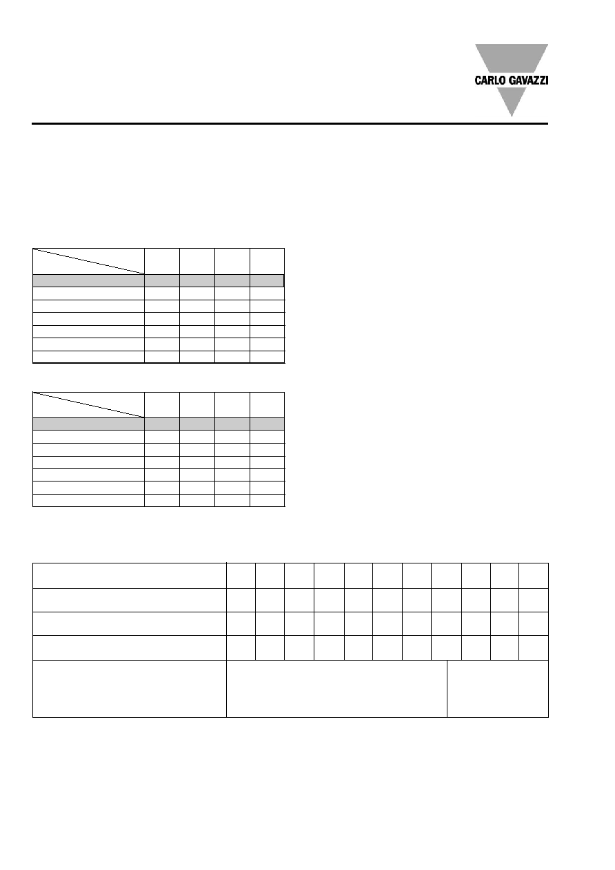
RSE .. 03 - B
Time between rampings
1
2
5
10
Ramp time (sec.)
I ramp (A)
RSE .. 12 - B
Time between rampings
1
2
5
10
Ramp time (sec.)
72
2.5 min 5 min
40 min
N/A
60
1.5 min 3 min
13 min 17 min
48
50 sec 1.5 min 5 min
10 min
36
30 sec
1 min
3 min
7 min
24
15 sec 40 sec 1.5 min 2.5 min
12
10 sec 20 sec 50 sec 70 sec
6
5 sec
9 sec
20 sec 40 sec
I ramp (A)
Recommended thermal-magnetic overload relay
Selection Chart
Thermal-magnetic overload relay and motor controller
Motor full load current (AACrms)
0.1 -
0.16 - 0.25 - 0.4 -
0.63 - 1.0 -
1.6 -
2.5 -
4 -
6.3 -
9 -
0.16
0.25
0.4
0.63
1.0
1.6
2.5
4
6.3
9
12
M 01
M 02 M 03 M 04 M 05 M 06 M 07 M 08 M 10 M 14 M 16
0.16
0.25
0.4
0.63
1
1.6
2.5
4
6.3
9
12.5
0.16 0.25
0.4
0.63
1
1.6
2.5
4
6.3
10
16
Overload relay type GV 2-
Manufacturer: Telemecanique
Overload relay type MS 325-
Manufacturer: ABB
Motor protection circuit breaker type KTA 3-25-
Manufacturer: Allan-Bradley/Sprecher + Schuh
RSE 22 12 - B
RSE 40 12 - B
RSE 48 12 - B
RSE 60 12 - B
Motor controller type:
127/220 V mains
230/400 V mains
270/480 V mains
400/690 V mains
RSE 22 03 - B
RSE 40 03 - B
RSE 48 03 - B
RSE 60 03 - B
Example:
Line voltage: 230/400 V
Motor 1.5 HP: 1.1 kW
Full load current: 2.9 A
Step 1:
Select overload relay:
In this example GV 2 - M 08,
MS 325 - 4 or KTA 3-25-4A
must be used.
Step 2:
Select motor controller:
For line voltage 230/400 V and
overload, relay GV 2 - M 08 or
MS 325 - 4 with a setting of
2.9 A type RSE 40 03 -B can
be selected.
N.B.: For motors with full load
current from 12 A to 40 A, see
types RSH and RSC/RSO.
18
15 sec 30 sec 1.5 min 2.5 min
15
12 sec 20 sec 60 sec 1.5 min
12
10 sec 20 sec 50 sec 70 sec
9
8 sec
12 sec 30 sec 50 sec
6
5 sec
9 sec
25 sec 40 sec
3
2 sec
5 sec
20 sec 35 sec
1.5
1 sec
2 sec
5 sec
5 sec
Applications