 | ÐлекÑÑоннÑй компоненÑ: RSMR4072 | СкаÑаÑÑ:  PDF PDF  ZIP ZIP |
RSMR(300905)1.eng
Specifications are subject to change (22.05.2006)
1
M-line Motor Controller
Rotary ramp selector
Rated operational voltage
Rated operational current
Ordering Key
Motor Controllers
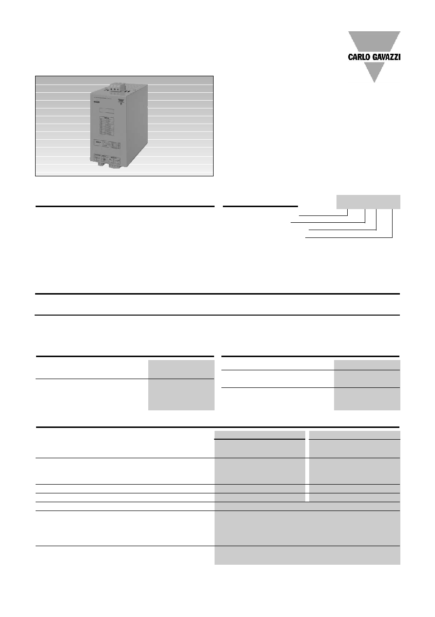
AC Semiconductor Motor Controller
Type RSMR
· Soft starting and stopping of 3-phase
squirrel cage motors
· 2 Phase controlled (without bypass relay)
· Reliable microprocessor control
· 10 pre-programmed ramping profiles
· Rated operational voltage up to 480VAC, 50/60 Hz
· Rated operational current up to 90A AC-53a
· LED status indicator
· Kickstart option for high torque loads
· Auxiliary relays for top of ramp and run
· Phase loss protection at starting
· Over-current "shear-pin" protection
Product Description
The RSMR is a microproces-
sor based soft starter for 3-
phase induction motors. A
rotary knob enables selection
from 10 pre-programmed
ramping profiles. The choice is
suggested by a list of popular
applications that corresponds
to the positions of the selec-
tor. No external supply is nec-
essary as starting and stop-
ping are controlled by closing
and opening a contact.
RSM R 40 90
Rated operational
Rated operational current I
e
voltage U
e
72A AC-53a
90A AC-53a
340-506 VAC, 50/60 Hz
RSMR4072
RSMR4090
Selection Guide
Load Ratings
RSMR4072
RSMR4090
IEC rated operational current Ie (AC-53a) @ 40/50/60ºC
72/57/43 A
90/72/54 A
Assigned motor rating @ 40ºC
400V
37kW/50HP
45kW/60HP
460V
40kW/54HP
45kW/60HP
Overload cycle to IEC/EN 60 947-4-2
72A: AC-53a: 5-4: 99-10
90A: AC-53a: 5-4: 99-10
Power dissipation at rated operational current
119W
144W
Number of starts per hour @ 40ºC
10 (starting interval 6 minutes)
Start duty
5 x FLC for 4 seconds
4 x FLC for 6 seconds
3 x FLC for 12 seconds
2 x FLC for 26 seconds
Shear-pin cut-off level
currents in excess of 5 x FLC for 500ms
Supply Specification
Rated operational voltage Ue through
L1, L2, L3
340-506VAC rms
Rated AC frequency
50/60 Hz ±2Hz
Input Specifications
Control supply
Internal
Control contacts S0, S1
close to start,
open to stop
Soft Stop Control
no more than 3m
from enclosure
2
Specifications are subject to change (22.05.2006)
* Above 40°C derate linearly by 1% of unit FLC per 100m to a max.
of 40% at 60°C.
RSMR
Standards
Markings
CE
Norms
IEC/EN 60947-4-2
Thermal Specifications
Operating temperature
*
0º to +
40ºC
(32º to +140ºF)
Storage temperature
-25º to +60ºC
(-13º to +140ºF)
General Specifications
Degree of protection
IP20 (IEC 60529)
Relative humidity max.
85% non-condensing,
not exceeding 50% @ 40ºC
Rated insulation voltage Ui
460V
Pollution degree
3
Ramp up time
1 to 15s
Ramp down time
0 to 15s
Application selection
10 position rotary switch
Status indicator LED
red continuous: active,
red intermittent: fault
Auxiliary relay contacts
Run 13,14
Normally open
Top
of ramp 23,24
Normally open
Auxiliary relay contact capacity
5A, 250V AC1
Installation altitude
Above 1000m derate
linearly by 1% of unit
FLC per 100m to a
maximum altitude of
2000m
Form Designation
Form 1
Rated Short Circuit Current (Iq)
20kA
Short Circuit Co-ordination
Type 1
Conductor Data
Power conductors
Size
16mm
2
to 35mm
2
(AWG 6 to 2)
Tightening torque
2.5Nm
Screw driver
Flat, size 7
Auxiliary conductors
Size
0.5mm
2
to 2.5mm
2
(AWG 20 to 14)
Tightening torque
0.5Nm
Screw driver
Flat, size 3
Ground/earth conductor
1.0mm
2
or
5mm earth stud
EMC Emission and Immunity Levels
ESD immunity
IEC 61000-4-2
6kVcontact or 8kV
air discharge
R F immunity
IEC 61000-4-6
140dBuV over 0.15-80MHz
R F immunity
IEC 61000-4-3
10V/m over 80/100MHz
Fast transient immunity
IEC 61000-4-4
2kV/5kHz
Surge immunity
IEC 61000-4-5
2kV line to gound
1kV line to line
Conducted RF emissions
EN55011 Class A
Radiated RF emissions
EN55011 Class A
Recommended Protection
RSMR..72
RSMR..90
Semiconductor fuse
Ferraz Shawmut, type PSC
Semiconductor fuse
Ferraz Shawmut, type PSC
250 A, body size 31,
250 A, body size 31,
Art.No. 6,6URD31D11A0250
Art.No. 6,6URD31D11A0250
or 6,6URD31EF0250
or 6,6URD31EF0250
Bussmann, type Zilox, 250 A,
Bussmann, type Zilox, 250 A,
body size 1, Art.No. 170M3116
body size 1, Art.No. 170M3116
Specifications are subject to change (22.05.2006)
3
RSMR
stop will be performed
according to the setting of
the rotary setup knob.
Soft-start and stop with
push-to-make and push-
to-break switches
(Fig. 4)
Pushing P1 soft-starts the
RSMR. Pushing P0 soft-
stops the RSMR. K is the
auxiliary contact of an exter-
nal mains contactor.
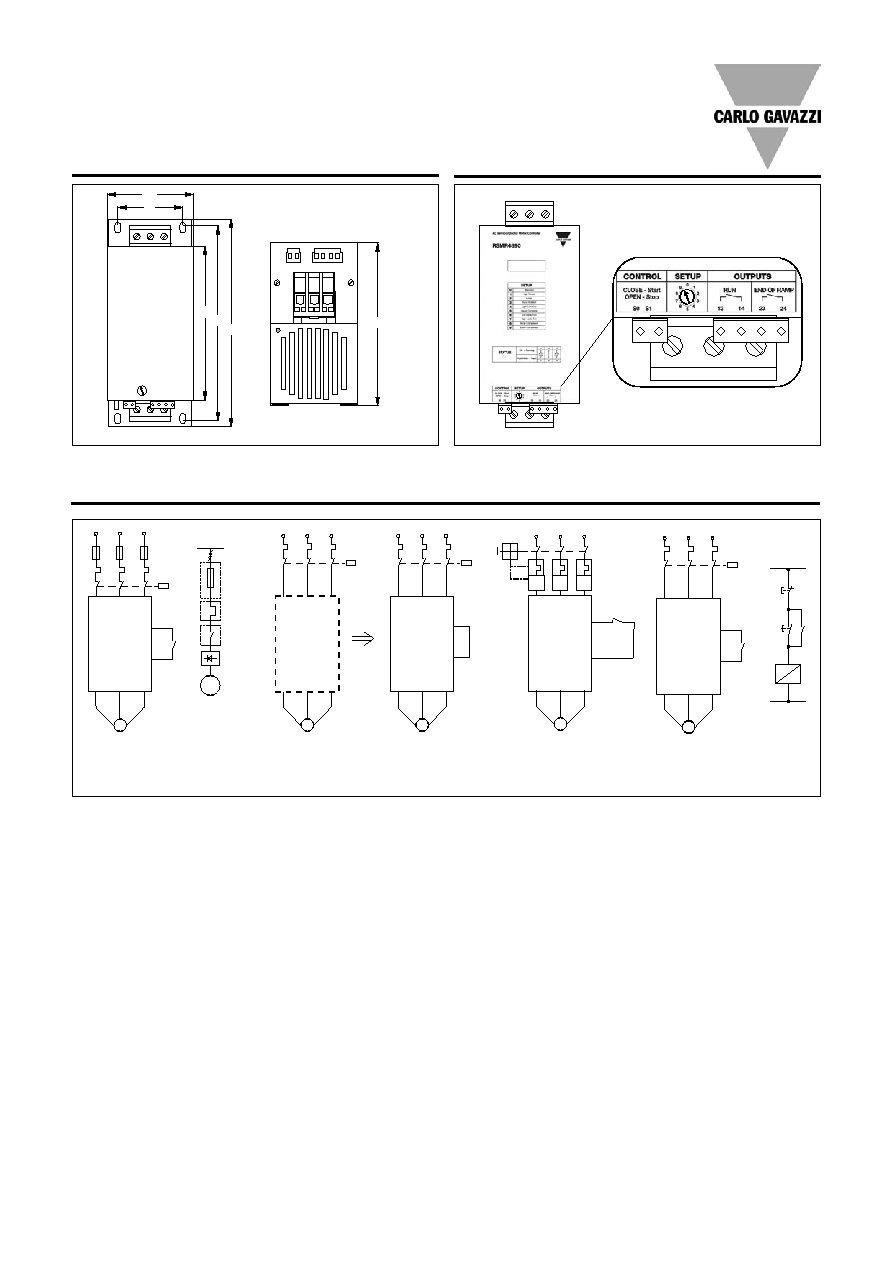
Control Diagrams and Applications
Fusing Considerations
(Fig.1)
This motor controller uses
semiconductors during run-
ning operation. Therefore the
semiconductors can be
damaged by short-circuit
currents. The best protec-
tion is with semiconductor
fuses.
Changing from Direct ON
Line start to soft start
(Line controlled soft-start)
(Fig. 2)
Changing a Direct On Line
start into a soft start is very
simple with the RSMR soft
starter:
1) Cut the cable to the motor
and insert the RSMR soft
starter.
2) Short the control input S0,
S1 with the link provided
3) Power up again - adjust
the start torque so the
motor starts turning
immediately after power is
applied.
When C1 is operated, the
motor controller will perform
soft-start of the motor. When
C1 is switched off, the motor
will stop (no soft-stop), the
motor controller will reset
and a new soft-start can be
performed.
Please note that the con-
troller does not insulate the
motor from the mains. A
mains contactor C1 is there-
fore needed.
Soft-start and stop with 2
position switch
(Fig. 3)
When P1 is closed, soft-start
of the motor will be per-
formed according to the set-
ting of the rotary setup knob.
When P1 is opened, soft-
Fig. 2 Starting via mains
contactor
S0
S1
L1
L2
L3
L1
L2
L3
U/T1
V/T2 W/T3
M
P1
Fig. 3 Control by
external switch
S0
S1
L1
L2
L3
L1
L2
L3
U/T1
V/T2 W/T3
M
L1
L2
L3
L1
L2
L3
U/T1
V/T2 W/T3
M
C1
C1
K
K
P1(ON)
P0(OFF)
S0
S1
K
L1
L2
L3
L1
L2
L3
U/T1
V/T2 W/T3
C1
M
Fig.4 Control via auxiliary
contact
RSMR
M
3~
S0
S1
K
L1
L2
L3
L1
L2
L3
U/T1
V/T2 W/T3
M
Fuse
Contactor
Overload
C1
Fig. 1 Main circuit with fuse
Dimensions
188
180
240
225
75
100
Terminal Diagram
L1 L2 L3
T1 T2 T3
All dimensions in mm
4
Specifications are subject to change (22.05.2006)
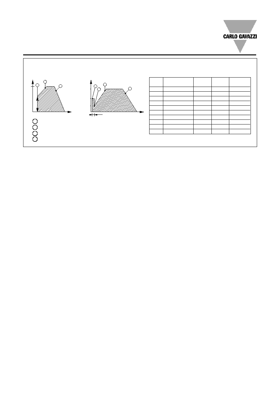
RSMR
Setup
Selection
Ramp-up
Initial
Ramp-down
position
switch
time s
voltage
time s
0
Standard
05
30%
10
1
High Torque
05
60%
05
2
Pump
05
40%
15
3
Pump kick-start
05
50%
15
4
Light conveyor
02
40%
10
5
Heavy conveyor
15
60%
10
6
Low inertia fan
10
30%
00
7
High inertia fan
15
50%
00
8
Recip. compressor
01
50%
00
9
Screw compressor
10
40%
00
Operation Diagram
Multi ramp starting strategies suitable for all applications are designed into the RSMR
3
1
2
4
100%
50%
25%
0.5s
3
1
2
1
Ramp-up time: time from zero load voltage to full load voltage.
2
Ramp-down time: time from full load voltage to zero load voltage.
3
Initial voltage: voltage at the start of the ramp-up function.
4
Kickstart: constant initial voltage delay before ramp-up.
Time
Time
Motor voltage
Motor voltage
Excluding setup position [3]
Setup position [3]