 | –≠–ª–µ–∫—Ç—Ä–æ–Ω–Ω—ã–π –∫–æ–º–ø–æ–Ω–µ–Ω—Ç: RTO1250 | –°–∫–∞—á–∞—Ç—å:  PDF PDF  ZIP ZIP |
Specifications are subject to change without notice (30.06.1999)
1
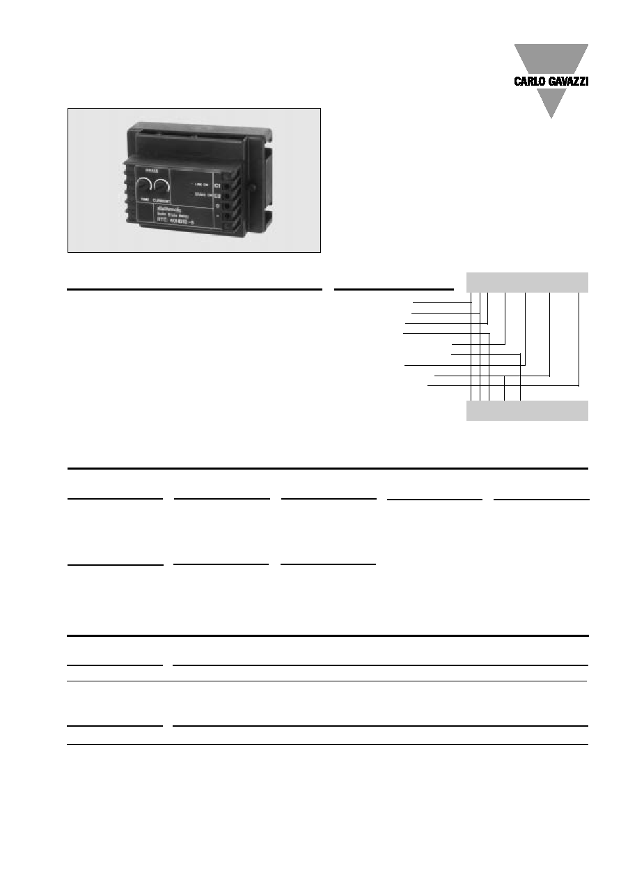
Solid State Relay
Dynamic braking
Control module
Output module
Rated operational voltage
Rated operational current
Control voltage
Non-rep. peak voltage
Rated op. frequency
∑
Control and output modules for dynamic
braking of 3-phase induction motors
∑
Rated operational current: 18.5, 30 and 60 A DC
∑
Rated operational voltage: Up to 400 VACrms
∑
Control voltage: 10 to 32 VDC
∑
LED indication for line ON and brake ON
Product Description
Dynamic braking is achieved
by introducing a DC current,
rectified from the mains,
through the motor windings.
The control module RTC 40
HD-12-. is used in combina-
tion with the output module
RTO 12.. to achieve dynamic
braking of 3-phase induction
motors with braking current
up to 60 A. The desired brak-
ing time and the required
brake current can be adjusted
Ordering Key
Type
Rated operational
Control voltage
Non-rep. peak
Rated operational
voltage
voltage
frequency
C: Control module
40: 120/208 VACrms
HD: 10 to 32 VDC
12: 1200 V
p
5: 50 Hz
±
3 Hz
230/400 VACrms
6: 60 Hz
±
3 Hz
Type Selection
Type
Non-rep. peak
Rated operational
voltage
current
O: Output module
12: 1200 V
p
10: 2 x 18.5 A DC
25: 2 x 30
A DC
50: 2 x 60
A DC
Non-rep. voltage
Rated operational current
8.5 A
30 A
60 A
1200 V
p
RTO 1210
RTO 1225
RTO 1250
Selection Guide
Control module
Rated operational frequency
50 Hz
60 H
230/400 VACrms
RTC 40 HD-12-5
RTC 40 HD-12-6
with the TIME and BRAKE
CURRENT potentiometers.
The control module, which is
separately supplied from an
external DC voltage source,
has LED indications for LINE
ON and BRAKE ON. The out-
put signal from the control
module is off 350 ms before
the brake current is intro-
duced. This signal can be
used to take away the AC
supply of the motor.
Motor Controllers
Dynamic Braking
Types RTC 40 HD12-./RTO 12..
RTO 1210
RTC 40 HD 12 - 5
2
Specifications are subject to change without notice (30.06.1999)
RTC 40 HD12-./RTO 12..
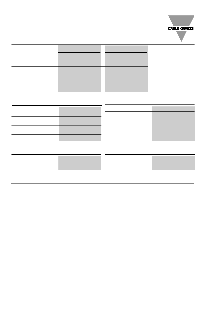
General Specifications Control Module
RTC 40 HD12-5
RTC 40 HD12-6
Operational voltage range
Line to line
190 to 440 VACrms
190 to 440 VACrms
Non-rep. peak voltage
1200 V
p
1200 V
p
Operational frequency range
47 to 52 Hz
57 to 63 Hz
Supply current
@ RUN, no output
30 mA @ 32 VDC
30 mA @ 32 VDC
@ BRAKE, no output
110 mA @ 32 VDC
110 mA @ 32 VDC
Approval
CSA
CSA
CE-marking
Yes
Yes
Control Input Specifications
Control voltage range
10 to 32 VDC
Motor running
8 VDC
Motor stopped
2 VDC
Adjust. braking current
Dependent on motor size
Adjust. braking time
1 to 40 s
Min. delay, stop to run
1 cycle
Remanence delay
350 ms
Mode of Operation
The control module RTC 40
HD12-5 (50 Hz)/RTC 40
HD12-6 (60 Hz) is used with
output module RTO 12.. to
achieve dynamic braking of
3-phase induction motors.
Dynamic braking is achieved
by passing direct current,
rectified from the mains,
through the motor windings.
The DC-current will then
produce a static field through
the short-circuited rotor, and
the induced rotor current will
create a torque opposite to
the direction of rotation.
Note:
This means that no braking
takes place when the motor
revolution is zero. The desir-
ed braking time can be set
by means of the BRAKE
TIME potentiometer. The
braking current can be ad-
justed by means of the
BRAKE CURRENT potentio-
meter to achieve motor stop
within the desired time.
Note:
Avoid excessive braking
current after the motor has
been stopped, as this will
create unnecessary heating
of the motor.
Since the RTC/RTO configu-
ration is only capable of
braking the motor, a starting
device is needed. Either a
Solid State Relay, e.g. Carlo
Gavazzi RZ, or a motor con-
troller RSC 40 HD12-./RSO
12.. can be connected to
the application.
To ensure safe operation the
starting device must be con-
trolled by the RTC output.
When the control voltage (ter-
minal C2) is removed, brak-
ing will take place.
The control module has LED
indication for line ON and
brake ON. The control mod-
ule also features remanence
delay. To avoid torque
shock, a delay of min. 350
ms passes from the moment
the motor contactor has
been released until DC vol-
tage is reapplied to the
motor windings.
To measure the braking cur-
rent, always use a true rms
ammeter with DC range.
In order to define the size of
the output module, it is ne-
cessary to find the resist-
ance between the two termi-
nals from the motor where
the brake module will be
connected. This resistance
is a combination of the resist-
ances of the motor windings
and is dependent on how
the motor is connected. In
star connection it is a series
connection of two windings
(see top of next page). In
delta connection it consists
of two windings connected
in parallel to the third win-
ding (see top of next page).
Control Output Specifications
Minimum output voltage
Power supply less 3.5 VDC
Output current
short-circuit protected
150 mA DC
Operating temperature
-20∞ to +80∞C (-4∞ to +176∞F)
Storage temperature
-40∞ to +100∞C (-40∞ to +212∞F)
Thermal Specifications Control Mod.
Insulation Control Module
Rated insulation voltage
Input to trigger outputs
4000 VACrms
Specifications are subject to change without notice (30.06.1999)
3
RTC 40 HD12-./RTO 12..
General Specifications Output Module
RTO 1210
RTO 1225
RTO 1250
Operational voltage range
Line to line
220 to 420 VACrms
220 to 420 VACrms
220 to 420 VACrms
Rated operational current AC1
18.5 ADC
30 ADC
60 ADC
Approval
CSA
CSA
CSA
CE-marking
Yes
Yes
Yes
RTO 1210
RTO 1225
RTO 1250
Non-rep. peak voltage
1200 V
p
1200 V
p
1200 V
p
Off-state leakage current
10 mA
10 mA
10 mA
On-state voltage drop
1.6 Vrms
1.6 Vrms
1.6 Vrms
I
2
t for fusing t=1-10 ms
130 A
2
s
310 A
2
s
1800 A
2
s
Critical dI/dt
50 A/µs
50 A/µs
50 A/µs
Non-rep. surge current t=20 ms 160 A
p
250 A
p
600 A
p
Output Specifications Output Module
RTO 1210
RTO 1225
RTO 1250
Operating temperature
-20∞ to +70∞C (-4∞ to +158∞F)
-20∞ to +70∞C (-4∞ to +158∞F)
-20∞ to +70∞C (-4∞ to +158∞F)
Storage temperature
-40∞ to +100∞C (-40∞ to 212∞F)
-40∞ to +100∞C (-40∞ to 212∞F)
-40∞ to +100∞C (-40∞ to 212∞F)
R
th
junction to case
1.4 K/W
1.0 K/W
0.5 K/W
Thermal Specifications Output Module
Rated insulation voltage
Output to case
4000 VACrms
Insulation Output Module
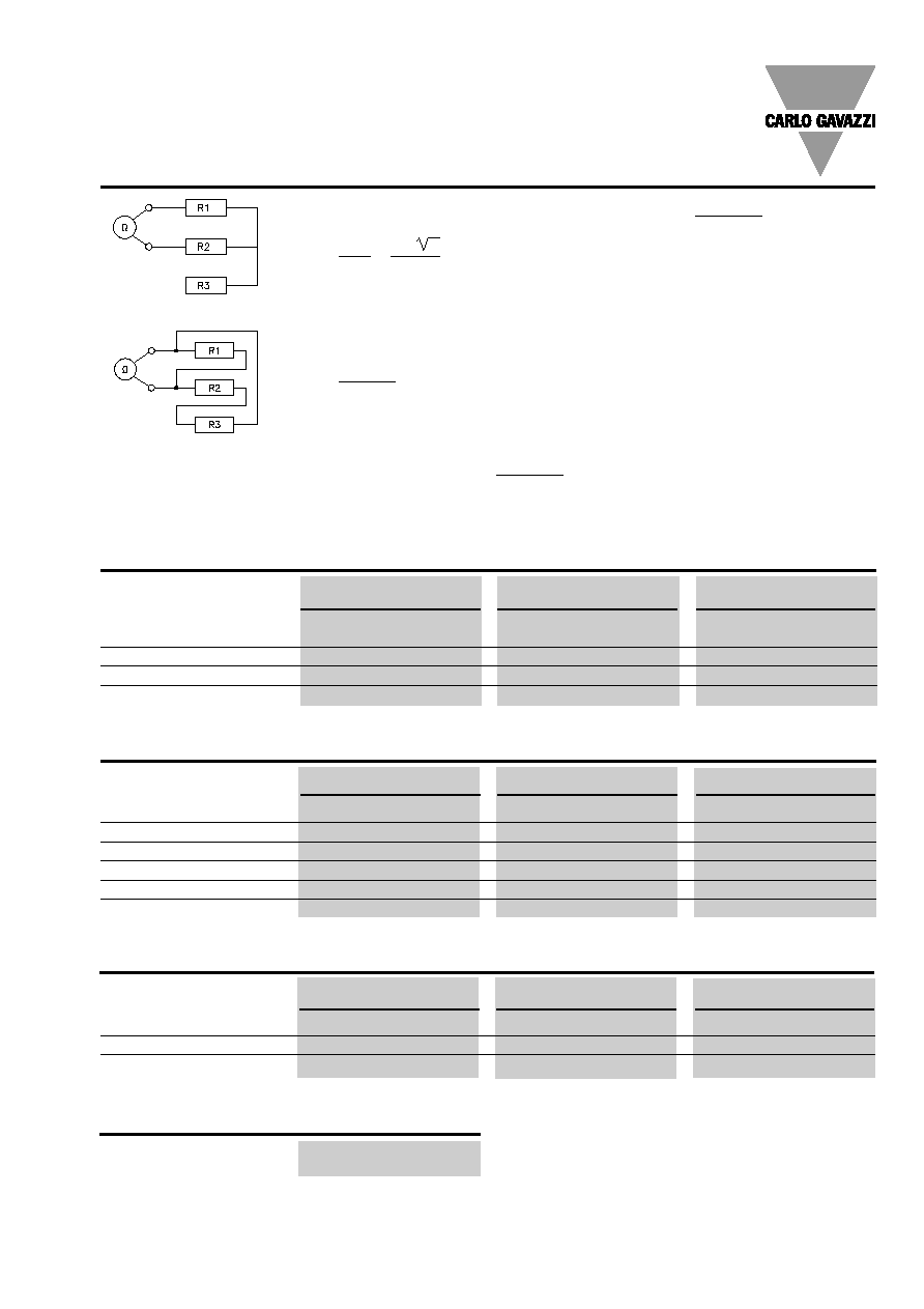
Mode of Operation (cont.)
Star
Delta
If the brake current is adjusted
to max., full half waves are
introduced to the motor, and
the DC voltage is calculated
as follows:
U
DC
=
U
max
=
U
n
x 2
= U
n
x 0.45
The max. current can be cal-
culated as follows:
I
max
=
U
n
x 0.45
R
where
R is a combination
of the windings mentioned
above.
Example: The resistance of
the motor winding is 5
.
The rated operational volt-
age is 400 VAC.
What is the max. current in
star connection and in delta
connection?
R star is R1 + R2 =
5 + 5
= 10
R delta is R1 parallel to
R2 + R3 = 3.3
.
The current is:
3.14
for the star connection, and
400 x 0.45
= 18 A
400 x 0.45
3.33
10
= 54 A
for the delta connection.
The output module has to be
selected accordingly (next
higher power rating).
4
Specifications are subject to change without notice (30.06.1999)
RTC 40 HD-12-./RTO 12..
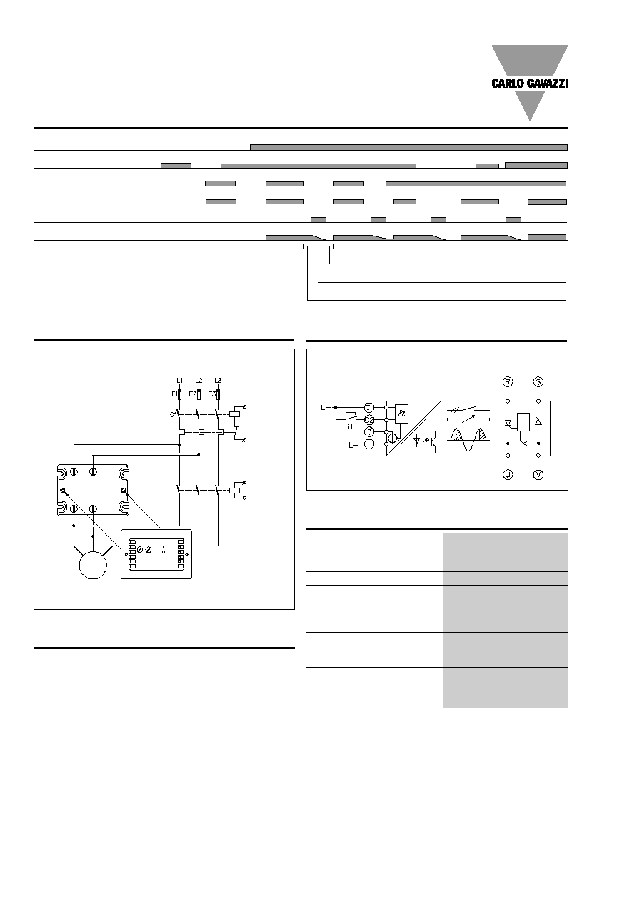
Operation Diagram
Control output
Control input C1
Control input C2
Output module activated
Mains voltage
Motor running
Adjustable braking time
Time delay, stop to run, min. 20 ms
T
d1
time delay, run to stop, min. 350 ms
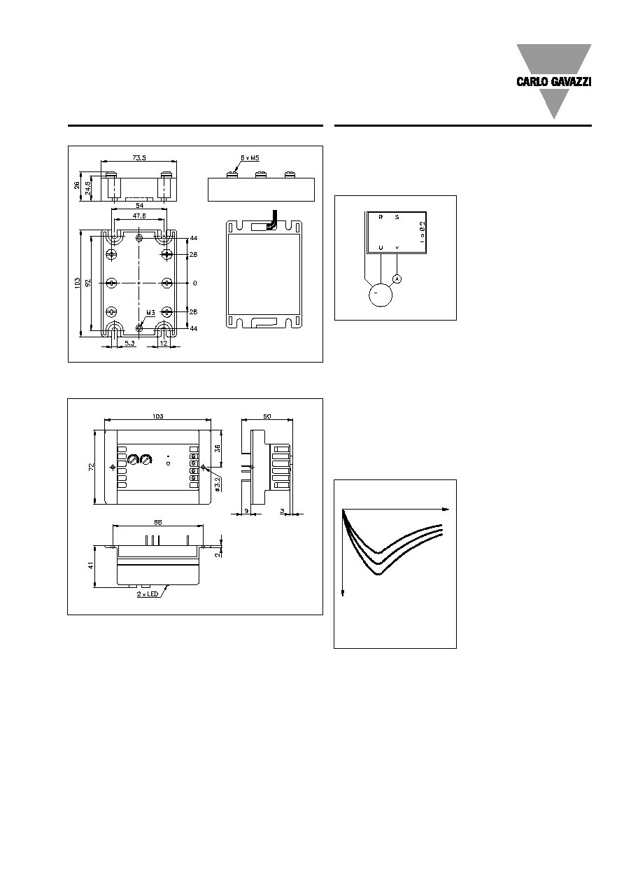
Wiring Diagram
Mounting and connection of control module and output module
Control inputs/outputs
M
Accessories
Heatsinks
For further information refer
Varistors
to "General Accessories".
Fuses
Temperature limit switch
Power supply
Functional Diagram
Mains input
Load output
Control inputs
and outputs
Housing Specifications
Weight
Approx. 275 g
Housing material
Noryl, glass-reinforced
Colour
Black
Base plate
Aluminium, nickel-plated
Potting compound
Polyurethane, black
Relay
Mounting scews
M5
Mounting torque
1.5 Nm
Control terminal
Mounting screws
M3
Mounting torque
0.5 Nm
Power terminal
Mounting screws
M5
Mounting torque
1.5 Nm
Specifications are subject to change without notice (30.06.1999)
5
RTC 40 HD-12-./RTO 12..
Applications
Measuring point for DC load
current
Note: When using a clamp-
meter, be sure that it is capa-
ble of measuring DC-current.
Brake current
Typical behaviour of braking
torque as a function of motor
speed: As will be seen from
the curve, the braking torque
will be relatively low at nomi-
nal motor speed. As the revo-
lution speed decreases, the
braking torque increases until
the speed approaches zero.
Then, the braking torque de-
creases. With zero speed the
braking torque is at zero.
Protection of the motor
A possible way of protecting
the motor against overheat-
ing where dynamic braking is
used is to mount a tempera-
ture sensor, PTC or Klixon,
between the motor windings.
Thermal relays will normally
be sensitive to the current
asymmetry occuring while
braking. The thermal relay may
trip undesirably.
Connection to the mains
As this type of brake relay has
a semiconductor between two
phases, it is always recom-
mended to protect it against
high surge currents as well as
possible voltage transients.
The protection consists of two
elements:
1. A semiconductor fuse rated
below the max. load integral
(I
2
t) for the output module.
2. A voltage-dependent resis-
tor (MOV) to prevent voltages
higher than the blocking volt-
age of the output modules.
Without MOV, voltage tran-
sients might trigger the output
module and subsequently
cause undesirable fuse blow-
ing.
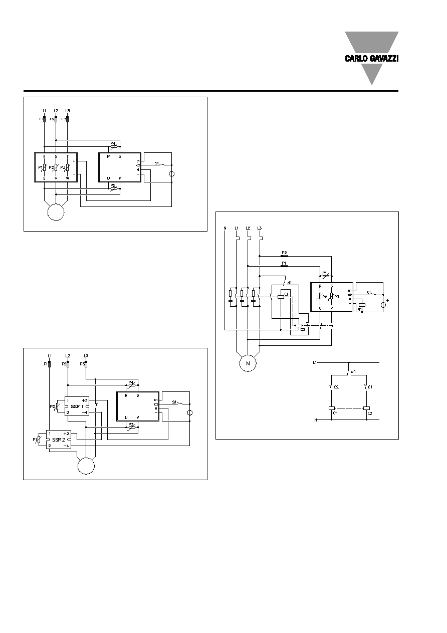
Connection to 3-phase SSR
F1 - F3: Ultrafast fuses with I
2
t
rated lower than the I
2
t value
of the output module.
P1 - P5: Varistors for 420 V
mains with a diameter of 20
mm.
Dimensions
RTO 12..
RTC 40 HD12-.
***
**
***
***
***
***
**
**
**
**
**
**
** =
±
0.4 mm
*** =
±
0.5 mm
Different settings of brake
current I
1
> I
2
> I
3
Motor speed
Torque
I
3
I
1
I
2
M
Use heatsink
compound
Temperature
limit switch
6
Specifications are subject to change without notice (30.06.1999)
Applications (cont.)
RTC 40 HD12-./RTO 12..
Connection to a 3-phase mechanical relay
Special precautions should
be taken where the driving el-
ement is a mechanical con-
tactor. The electrical voltage
peaks from the contactor must
be dampened by the use of
RC snubbers.
Varistor: 520 K 420 Siemens
RC: PMR 209 Rifa 47
/0.1 µF
d1: Feme MZP
Fuse: See "General Accessories".
The output of the braking
module is disconnected from
the motor terminals when the
motor is running and is con-
nected only when the motor
is in brake or stop mode. This
feature together with a me-
chanical and electrical inter-
lock (dotted line) between
motor and brake relay will help
to reduce the risk of malfunc-
tion.
S1 closed: The motor is run-
ning.
S1 opens: The adjusted cur-
rent brakes the motor within
the adjusted time.
If S1 is closed before the end
of a braking cycle, the relays
will return to RUN mode within
0.1 s.
Note: Motor protecting relay
is not shown.
F1 - F3: Ultrafast fuses with I
2
t
rated lower than the I
2
t value
of the output.
P1 - P4: Varistors for 420 V
mains with a diameter of 20
mm.
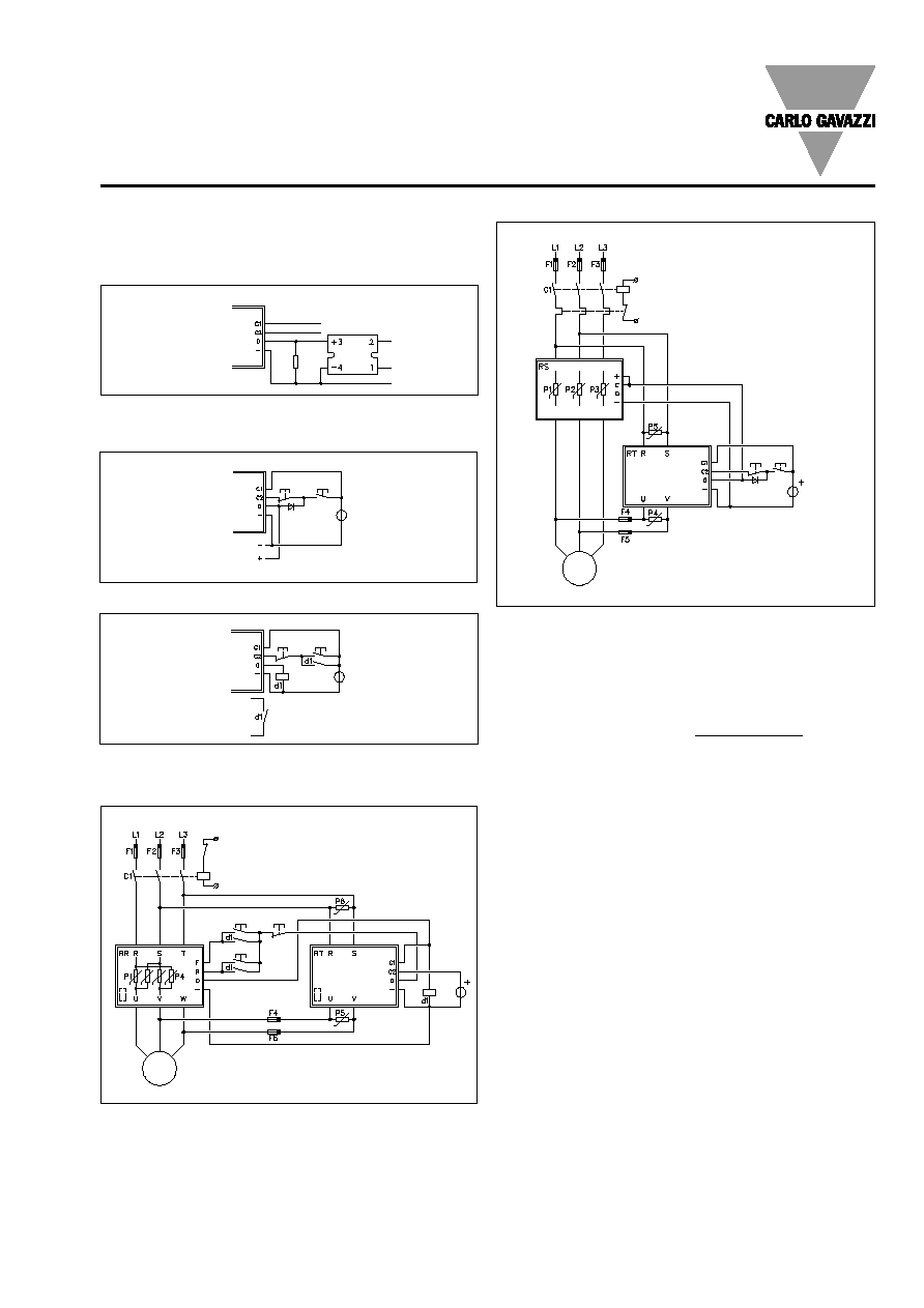
Connection to two 1-phase SSRs
Power supply
10 to 32 V
M
Power
supply
M
SSR 1, SSR 2: Carlo Gavazzi
type RA 48 xx-D 12 (1200 V
blocking voltage).
S1 closed: The motor is run-
ning.
S1 opens: The adjusted cur-
rent brakes the motor within
the adjusted time.
If S1 is closed before the end
of a braking cycle, the relays
will return to RUN mode within
0.1 s.
RS 302 440 24
Motor protection relay
Power supply
24 VDC
Mechanical
interlock
Motor relay
Brake relay
F1 - F3: Ultrafast fuses with I
2
t
rated lower than the I
2
t value
of the output module. F3 is
optional since there is no
semiconductor in L3.
P1 - P3: Varistors for 420 V
mains with a diameter of 20
mm.
When S1 is closed, the motor
is running.
When S1 is opened, the mo-
tor brakes and stops.
Note: The max. allowable de-
lay time for switching off is
350 ms. Do not use more than
one auxiliary relay.
The d1 relay could also be a
Solid State Relay, e.g. Carlo
Gavazzi relay type RP 130
240-2-0.
Fuse
*
* SSR 3: If switching of all three pha-
ses is desired.
Specifications are subject to change without notice (30.06.1999)
7
Applications (cont.)
RTC 40 HD12-./RTO 12..
Interconnection of soft starting and braking SSRs
Power
supply
Pilot voltage
Start
Stop
F1 - F5: Ultrafast fuses with I
2
t
rated lower than the I
2
t value
of the relevant output mod-
ules.
P1 - P5: Varistors for 420 V
mains with a diameter of 20
mm.
Thermal considerations
Motor
Dynamic braking of 3-phase
induction motors creates
power dissipation in the mo-
tor. The DC current dissipates
power in the stator windings,
and the stored energy in the
rotating machine is dissipated
in the rotor during braking.
Consequently, the best way of
protecting the motor will be to
install temperature sensors in
the motor windings.
Solid State Relay
Due to the relatively high
power dissipation in the mo-
tor the RUN and BRAKE mode
ratio is normally less than 0.1.
This gives negligible power
dissipation in the braking Solid
State Relay. Under normal
conditions it will be sufficient
to mount the relay on to the
chassis. If no metal backplate
is available, a heatsink must
be used:
RTO 1210 R
th
= 2.5 K/W
RTO 1225 R
th
= 2.5 K/W
RTO 1250 R
th
= 1 K/W
The heatsinks are sufficient
for ambient temperatures up
to 60
∞
C (140
∞
F).
F1 - F5: Ultrafast fuses with I
2
t
rated lower than the I
2
t value
of the relevant output mod-
ules.
P1 - P6: Varistors for 420 V
mains with a diameter of 20
mm.
Pilot voltage
Forward Stop
Reverse
Power supply
24 VDC
Interconnection of braking and reversing SSRs
M
With auxiliary relay
Stop
Start
Power
supply
To driver
relay
Stop
Start
D = 1N4007
To driver
relay(s)
Power
supply
With auxiliary diode
Start - stop function
(only control circuit is shown)
Out
When using Solid State Re-
lays, a resistor of 1 k
should
be connected between out-
put (0) and negative (-) on the
RTC control unit to ensure
that the output voltage from
the RTC control unit is lower
than the drop-out voltage
for the Solid State Relay.
< 0.1
Brake time
Run + Brake time
1 k
,
1 W
1/L
1
3/L
2
5/L
3
2/T
1
4/T
2
6/T
3
M