
Specifications are subject to change without notice VCPDINDS080906
1
∑
Virtual COM port serial device server
∑
RS232, RS422, RS485 serial port available
∑
Auto detecting 10/100 Mbps Ethernet interface
∑
Real COM drivers for Windows
∑
Easy-to-use configuration software suite
∑
Cigarette pack size
∑
Wall and DIN-rail mounting
Product Description
VCP DIN provides a data
communication solution for
connecting Windows hosts
(as PowerSoft) to the Carlo
Gavazzi energy meters and
power analysers over a
TCP/IP Ethernet network
(LAN, Internet). VCP DIN
works like an add-on single-
port serial board to the PC
server, but with the major
advantage of exploiting the
TCP/IP network. Although it
connects through the virtual
link of the Ethernet, the port
Energy Management
Accessories
Type VCP-DIN
on VCP DIN is recognized
as a real COM port by Win-
dows. VCP DIN provides
both the basic transmit/
receive data functions, as
well as RTS, CTS, DTR,
DSR, and DCD control sig-
nals. VCP DIN is supplied
with a utility program pro-
viding a simple step-by-
step installation procedure
and a maintenance wizard
that allows an easy access
to the instruments.
Model
Power supply
adapter
How to order
VCP DIN UK
Type Selection
Power supply adapter
none: 230VAC to 12VDC power supply adapter, EU plug
UK:
230VAC to 12VDC power supply adapter, UK plug
US:
120VAC to 12VDC power supply adapter, US plug
LAN
Ethernet
10/100 Mbps
Connector
RJ45
"Link" indication
LED, yellow
Protection
Built-in 1.5kV magnetic
isolation
Serial
Interface
DIP-switch selectable
among RS232, RS422 and
RS485
Connector
Female DB9
"Ready" indication
LED, green (100Mbps),
orange (10Mbps)
RS232 signals
TxD, RxD, RTS, CTS, DTR,
DSR, DCD, GND
RS422 signals
Tx+, Tx-, Rx+, Rx-, RTS+,
RTS-, CTS+, CTS-, GND
RS485 (2-wire) signals
Data+, Data-, GND
RS485 (4-wire) signals
Tx+, Tx-, Rx+, Rx-, GND
Protection
15kV ESD for all signals
Serial communication parameter
Parity
None, even, odd, space, mark
Data Bits
5, 6, 7, 8
Stop Bits
1, 1.5, 2
Flow control
RTS/CTS, XON/XOFF
Speed
50bps to 230.4kbps
Nodes and max distance
1
unit load
up to 32 (1200m)
1/5 unit load
up to 160 (1200m)
1/8 unit load
up to 247 (1200m)
Protocols
DHCP, Boot P, Telnet, TCP,
VDP, IP, ICMP, ARP
Windows compatibility
Windows 95/98/ME/NT/
2000/XP/2003
Input/Output specifications
DC supply
9 to 30VDC
Power-on indication
LED, red
Power consumption
300mA @ 9V (max)
AC/DC power supply adapter Included (see type selec-
tion)
Supply specification
2
Specifications are subject to change without notice VCPDINDS080906
VCP DIN
Operating temperature
0∞C to +55∞C (32∞F to 131∞F)
5 to 95% RH (non-condens-
ing)
Storage temperature
-20∞C to +85∞C (-4∞F to
185∞F) 95% RH (non-con-
densing)
EMC
EN61000-6-1
EN61000-6-3
FCC part 15 subpart B
Standard compliance
Safety
EN60950, UL60950
Medical
EN60601-1-2 class B,
EN55011
Approvals
CE, cULus, FCC, TÐV, GS
Housing
Dimensions (WxHxD)
90 x 100 x 22 mm
Material
SECC sheet metal (1mm)
Protection degree
IP30
Weight
Approx. 880 g (packing
included)
Standard accessories
DIN-rail mounting kit
9-pole serial cable
9-pole null-modem adapter
Configuration software
Hardware and software
manuals.
Quick installation guide
General specification
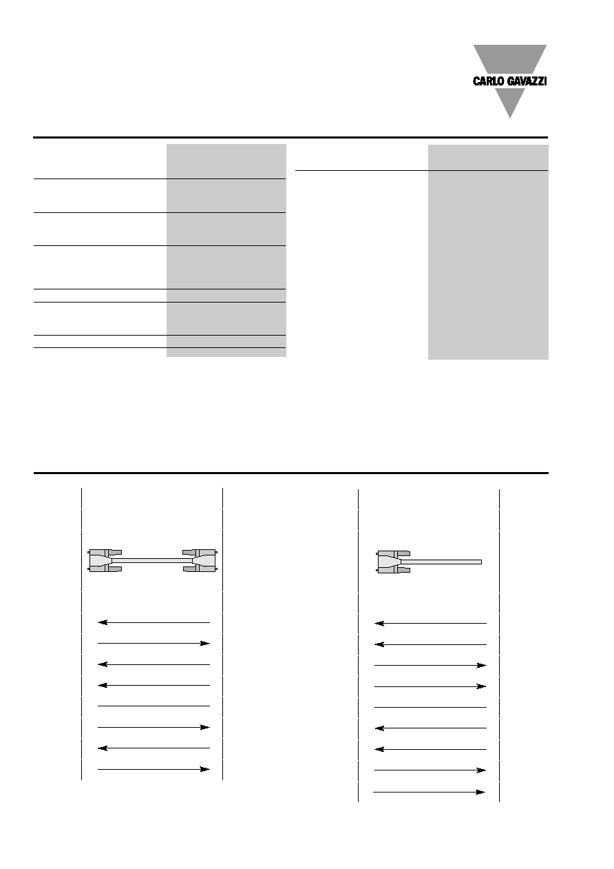
Wiring diagrams
DB9
Female
DB9
Female +
DB9
Male
DB9
Female
null-modem
Male
VCP-DIN
RS232
Device
9 pins
Cable wiring
DCD 1
1 DCD
TxD 2
3 RxD
RxD 3
2 TxD
DSR 4
6 DTR
GND 5
5 GND
DTR 6
4 DSR
CTS 7
8 RTS
RTS 8
7 CTS
DB9
Female
DB9
Male
VCP-DIN
RS422
Device
9 pins
Cable wiring
RxD- 1
TxD-
RxD+ 2
TxD+
TxD- 3
RxD-
TxD+ 4
RxD+
GND 5
GND
CTS- 6
RTS-
CTS+ 7
RTS+
RTS+ 8
CTS+
RTS- 9
CTS-
RS232 Wiring
Fig. 1
RS422 Wiring
Fig. 2
Note:
the serial cable and the null-modem adapter are to
be used
