 | –≠–ª–µ–∫—Ç—Ä–æ–Ω–Ω—ã–π –∫–æ–º–ø–æ–Ω–µ–Ω—Ç: CRD4360-9 | –°–∫–∞—á–∞—Ç—å:  PDF PDF  ZIP ZIP |
Preliminary Product Information
This document contains information for a new product.
Cirrus Logic reserves the right to modify this product without notice.
1
Copyright
©
Cirrus Logic, Inc. 2000
(All Rights Reserved)
P.O. Box 17847, Austin, Texas 78760
(512) 445 7222 FAX: (512) 445 7581
http://www.cirrus.com
CrystalClearTM AC '97 Four Channel PCI Audio Reference Design
Features
l
CS4630 PCI audio controller and CS4294
four channel AC`97 audio codec
l
20-bit D to A conversion (DAC)
l
18-bit A to D conversion (ADC)
l
S/PDIF (IEC-958) optical digital input and
output
l
Complete suite of Analog I/O connections:
≠ Line, Mic, CD and Aux Inputs
≠ Line Front, and Line Rear Outputs
l
Joystick/MIDI Interface
l
2-layer low cost PC board
l
PCI Audio Accelerator add-in card designed
to meet AC `97 version 2.1 specification
l
Exceeds Microsoft's
Æ
PC 99 audio
performance requirements.
Description
The CRD4630-9 PCI add-in board reference design
showcases Cirrus Logic's CS4630 audio controller and
the CS4294 audio codec. This card features four chan-
nel 20-bit analog audio outputs and S/PDIF digital audio
inputs and outputs.
The CRD4630-9 reference design is available by order-
ing the CMK4630-9 manufacturing kit. This kit includes
a full set of schematic design files (OrCAD
Æ
7.2 format),
PCB job files (PADS
Æ
ASCII), PCB artwork files, and bill
of materials. The design is production ready or can be
easily modified to meet your specific design goals.
ORDERING INFO
CMK4630-9 (Manufacturing Kit)
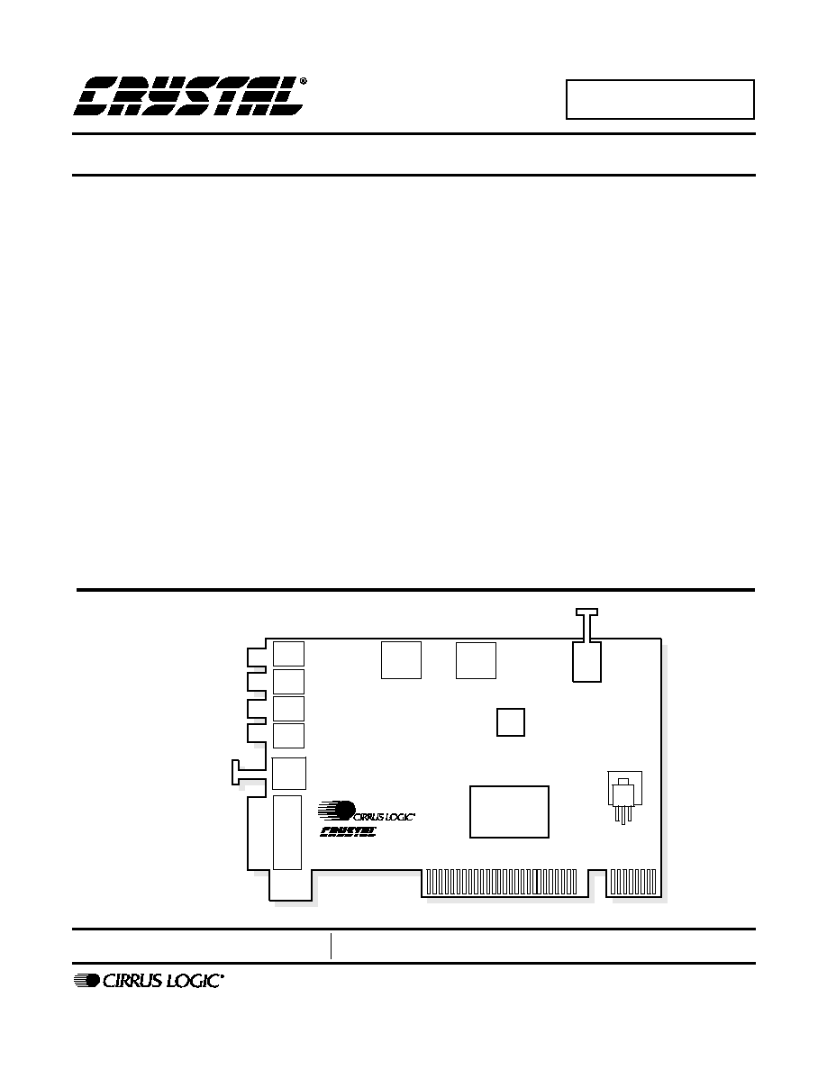
CS4630
CS4294
CD IN
AUX IN
MIC IN
LINE IN
LINE OUT FRONT
LINE OUT REAR
SPDIF OUT
POWER
CRD4630-9
MIDI /
JOYSTICK
SPDIF IN
JUN `00
DS445RD9A1
CRD4360-9

CRD4630-9
2
DS445RD9A1
TABLE OF CONTENTS
1. GENERAL INFORMATION ...................................................................................4
2. SCHEMATIC DESCRIPTION ................................................................................4
2.1 Analog Inputs (1) ........................................................................................4
2.2 Analog Inputs (2) ........................................................................................4
2.3 Analog Outputs ..........................................................................................5
2.4 Anti-Pop Circuitry ........................................................................................5
2.5 CS4294 Audio Codec .................................................................................5
2.6 CS4630 PCI Controller ...............................................................................5
2.7 MIDI and Joystick Connection ....................................................................6
2.8 S/PDIF Output ...........................................................................................6
2.9 PCI Bus Connection ...................................................................................6
2.10 Power Supply ............................................................................................6
2.11 Component Selection ...............................................................................6
2.12 EMI Components ......................................................................................7
3. GROUNDING AND LAYOUT ................................................................................7
3.1 Partitioned Voltage and Ground Planes .....................................................7
3.2 CS4294 Layout Notes .................................................................................7
4. REFERENCES .......................................................................................................8
4.1 ADDENDUM ...............................................................................................8
5. BILL OF MATERIALS .........................................................................................25
Contacting Cirrus Logic Support
For a complete listing of Direct Sales, Distributor, and Sales Representative contacts, visit the Cirrus Logic web site at:
http://www.cirrus.com/corporate/contacts/
Microsoft , Windows 95, Windows 98 and Windows Millennium and WHQL is registered trademark of Microsoft.
CrystalClear is a trademark of Cirrus Logic, Inc.
Intel is a registered trademark of Intel Corporation.
OrCAD is a registered trademark of OrCAD, Inc.
PADS is a registered trademark of, PADS Software, Inc.
Preliminary product information describes products which are in production, but for which full characterization data is not yet available. Advance product information
describes products which are in development and subject to development changes. Cirrus Logic, Inc. has made best efforts to ensure that the information contained
in this document is accurate and reliable. However, the information is subject to change without notice and is provided "AS IS" without warranty of any kind (express
or implied). No responsibility is assumed by Cirrus Logic, Inc. for the use of this information, nor for infringements of patents or other rights of third parties. This
document is the property of Cirrus Logic, Inc. and implies no license under patents, copyrights, trademarks, or trade secrets. No part of this publication may be
copied, reproduced, stored in a retrieval system, or transmitted, in any form or by any means (electronic, mechanical, photographic, or otherwise) without the prior
written consent of Cirrus Logic, Inc. Items from any Cirrus Logic website or disk may be printed for use by the user. However, no part of the printout or electronic
files may be copied, reproduced, stored in a retrieval system, or transmitted, in any form or by any means (electronic, mechanical, photographic, or otherwise) with-
out the prior written consent of Cirrus Logic, Inc.Furthermore, no part of this publication may be used as a basis for manufacture or sale of any items without the
prior written consent of Cirrus Logic, Inc. The names of products of Cirrus Logic, Inc. or other vendors and suppliers appearing in this document may be trademarks
or service marks of their respective owners which may be registered in some jurisdictions. A list of Cirrus Logic, Inc. trademarks and service marks can be found
at http://www.cirrus.com.

CRD4630-9
DS445RD9A1
3
LIST OF FIGURES
Figure 1. Block Diagram .................................................................................................... 9
Figure 2. Analog Inputs (1) .............................................................................................. 10
Figure 3. Analog Inputs (2) .............................................................................................. 11
Figure 4. Analog Outputs ................................................................................................. 12
Figure 5. Anti-Pop Circuitry ............................................................................................ 13
Figure 6. CS4294 AC'97 Audio Codec ............................................................................ 14
Figure 7. CS4630 Controller ............................................................................................ 15
Figure 8. MIDI and Joystick Control ................................................................................ 16
Figure 9. SDPIF ............................................................................................................... 17
Figure 10. PCI Bus Connection ....................................................................................... 18
Figure 11. Power Supply ................................................................................................ 19
Figure 12. PCB Layout: Assembly Drawing .................................................................... 20
Figure 13. PCB Layout: Top Layer .................................................................................. 21
Figure 14. PCB Layout: Bottom Layer ............................................................................. 22
Figure 15. PCB Layout: Drill Drawing .............................................................................. 23
Figure 16. PCB Layout: Silkscreen .................................................................................. 24

CRD4630-9
4
DS445RD9A1
1. GENERAL INFORMATION
The CRD4630-9 is a production grade reference
design that demonstrates the four channel capabili-
ty of the CS4630 PCI audio controller and the
CS4294 audio codec. The CRD4630-9 has a rich
feature set and industry leading audio performance.
In order to maintain high audio quality, careful
consideration has been given to component selec-
tion and PC layout.
The CS4294 codec has four 20-bit DACs, a stereo
18-bit ADC and a very flexible analog audio mixer.
It also features three stereo line level analog inputs,
a microphone input, and a stereo pseudo-differen-
tial CD input. The input signals can be routed to the
ADC for recording or mixed together for recording
and direct playback. The CS4294 has 64 registers
that are used to control its various features such as
volume levels, mutes and signal routing. The
CS4294 maintains high audio quality throughout
its signal chain and exceeds the Microsoft
Æ
PC-99
audio performance specification.
The CS4630 is a high performance PCI Audio Ac-
celerator. The CS4630 streams digital audio data
and MIDI over the PCI bus and performs sophisti-
cated digital audio processing.
The CS4630's audio 420 MIPs DSP core is opti-
mized for handling complex signal processing
tasks such as Sensaura 3D sound, wavetable syn-
thesis and graphic equalization. The CrystalClear
Æ
Stream Processing DSP core is supported by a bus
mastering PCI interface and a built-in dedicated
DMA engine with hardware scatter-gather support.
These functions ensure extremely efficient transfer
of audio data streams with minimum loading of the
host CPU.
The CS4294 codec and the CS4630 controller com-
municate through a 5-wire serial digital link known
as the AC-Link. The AC-Link is used to transfers
digital audio between the two devices. It is also
used to send commands from the CS4630 to the
CS4294's registers. For more information on the
AC-Link, see the Intel
Æ
AC'97 version 2.1 speci-
fication.
2. SCHEMATIC DESCRIPTION
The block diagram in Figure 1 illustrates the inter-
connections between the schematic pages. The fol-
lowing are descriptions of the other pages
contained in the schematics.
2.1
Analog Inputs (1)
The Line Input in Figure 2 is connected from the
input jack to the CS4294 through a 6 dB voltage di-
vider and AC coupling capacitors. The voltage di-
vider allows Line In signal levels of up to 2 Vrms.
The 10
µ
F AC coupling capacitor values are used
to minimize the low frequency roll-off.
The microphone circuit buffers, amplifies and fil-
ters the incoming signal from an external micro-
phone. It also provides low voltage phantom power
for electret microphones. This circuit uses a Mo-
torola MC33078D low noise dual op-amp. One of
the op-amps provides 18 dB gain stage for the mi-
crophone. The other op-amp buffers the phantom
power supply for the mic. The phantom power is
derived from the +5 V analog supply and buffered
to provide a maximum of 4.2 V with no load and a
minimum of 2.0 V under a 0.8 mA load, as re-
quired by PC 99. The microphone circuit was de-
signed for 3 dB rolloffs at 60 Hz and 15 kHz as
specified in PC-99.
2.2
Analog Inputs (2)
The Aux Input in Figure 3 is connected from the in-
put jack to the CS4294 through a 6 dB voltage di-
vider and AC coupling capacitors. The voltage
divider allows input signal levels of up to 2 Vrms.
The 10
µ
F AC coupling capacitor values are used
to minimize the low frequency roll-off.
The CS4294 has a pseudo-differential CD input
that minimizes common mode noise and interfer-
ence. The CD signals act as one side of the differ-
ential inputs and CD_COM as the other. CD_COM

CRD4630-9
DS445RD9A1
5
is used as the common return path for both the left
and right channels. For good common mode rejec-
tion performance, the voltage divider resistors for
CD_COM have been set to half the value of those
for CD L and R inputs.
There are provisions for two types of analog audio
CD connectors. J4 is for the standard ATAPI con-
nector and J2 for the legacy 2 mm Mitsumi connec-
tor. You can install only one of the two connectors,
because the footprints of J2 and J4 are on top of
each other.
2.3
Analog Outputs
The analog output circuit in Figure 4 drives the
front and rear audio signals in a four channel audio
system, or line out and headphone out in a two
channel audio system.
The Line Out Front L/R stereo outputs are driven
from the Line_Out left and right output pins of the
CS4294 through a pair of Motorola MC33078 op-
amps. The MC33078 is a high performance low
noise op-amp well suited for audio applications.
This output is designed to drive high impedance
loads (10 K
).
The Line Out Rear L/R stereo outputs are driven
from the Alt_Line_Out left and right output pins of
the CS4294 through a pair of Motorola TDA1308
op-amps. The TDA1308 is a high performance op-
amp capable of driving 32
loads. This makes it
ideal for driving low impedance headphones.
2.4
Anti-Pop Circuitry
Figure 5 shows the anti-pop circuity. During power
up, transistors Q1, Q2, Q4, and Q5 momentarily
mute the Front and Rear outputs to help suppress
transients.
2.5
CS4294 Audio Codec
The audio codec is shown in figure 6. The input sig-
nals to the codec come from the analog inputs in
Figures 2 and 3. The output of the codec go to the
analog output circuitry in Figure 4. Each of the out-
puts has a 680 pF capacitor to analog ground.
These capacitors are part of a signal pole lowpass
output filter.
The AFLT1 and AFLT2 pins have 1000 pF capac-
itors to analog ground. These capacitors in combi-
nation with some internal resistors provide a single
pole lowpass filter at the inputs of the ADCs. No
other input filtering is required.
The FLT3D, FLTI, and FLTO pins are a part of the
internal analog 3D enhancement filter.
The AC-Link requires series termination resistors
to prevent reflections. These are normally placed as
close as possible to the transmitting end of a partic-
ular AC-Link signal. Both SDATA_IN and
BIT_CLK are outputs of the CS4294 and each have
a 47
series termination resistors.
The CS4294 is powered by separate analog and
digital power supplies, each with their own ground
return, AGND for analog ground, and DGND for
digital ground. Each power pin needs separate de-
coupling capacitors. The CRD4630-9 uses a 0.1 uF
ceramic capacitor for each 3.3 V digital supply pin
along with a common 10 uF bulk capacitor. Each of
the 5 V analog pins uses a 0.1 uF decoupling ca-
pacitor. These are placed as close to their respec-
tive pins as possible.
2.6
CS4630 PCI Controller
The CS4630-9 controller in Figure 7 acts as a
bridge between the computers PCI bus and the co-
dec. ASYNC and ASDOUT are AC-Link signals
originating at the CS4630 and both require 47
series termination resistors close to the controller.
An external EEPROM, U7, is used to provide Ven-
dor ID and Subsystem ID to the CS4630 at power
up. The EEPROM connects to the CS4630 through
a data and clock line, EEDAT and EECLK. The
EEPROM interface is enabled by connection the
EEPDIS pin to digital ground.
The CS4630 requires three power supplies voltag-
es: +3.3 V, +5 V and +2.5 V. PCIVDD supplies