SPECIFICATIONS
MODEL
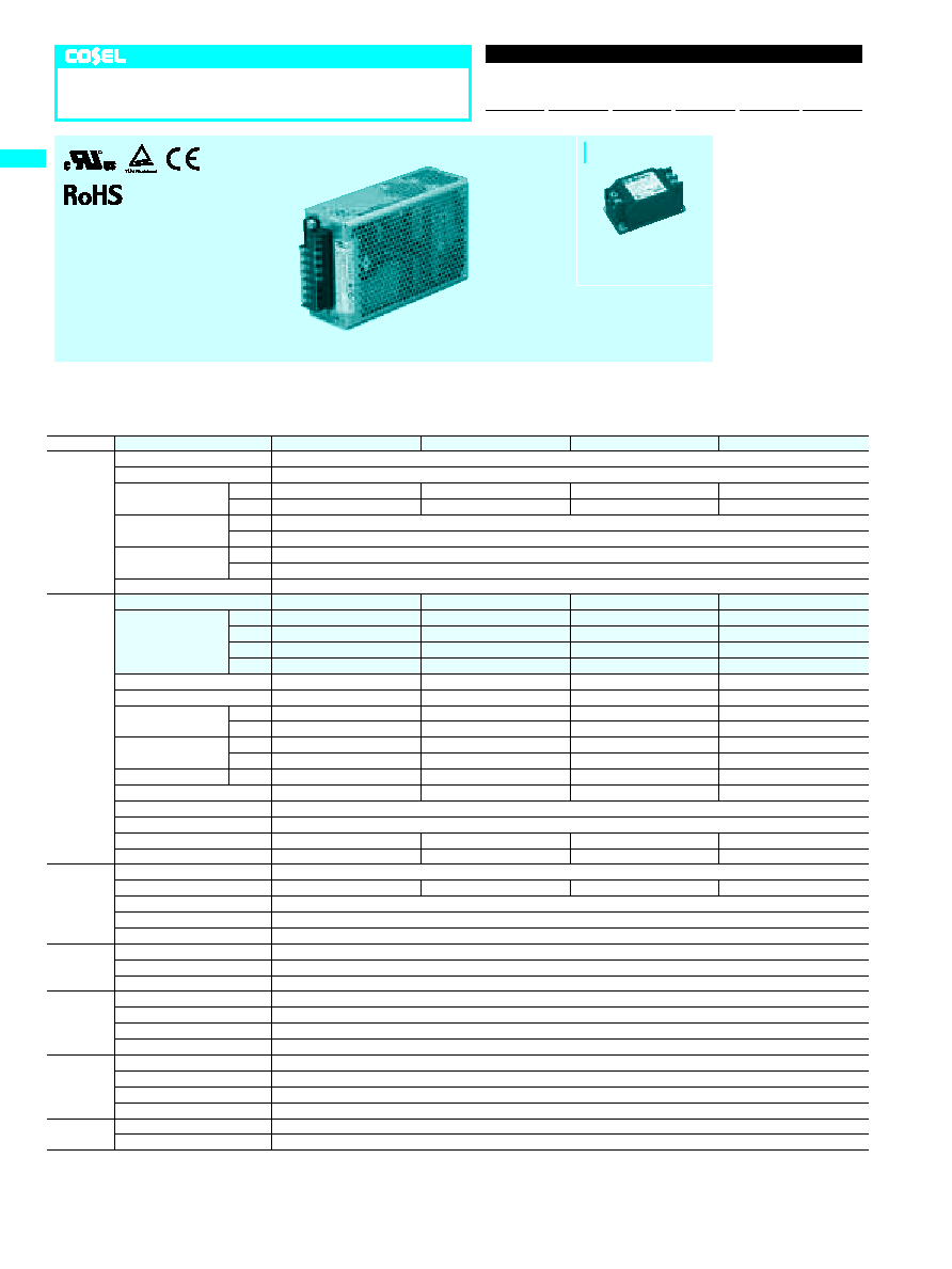
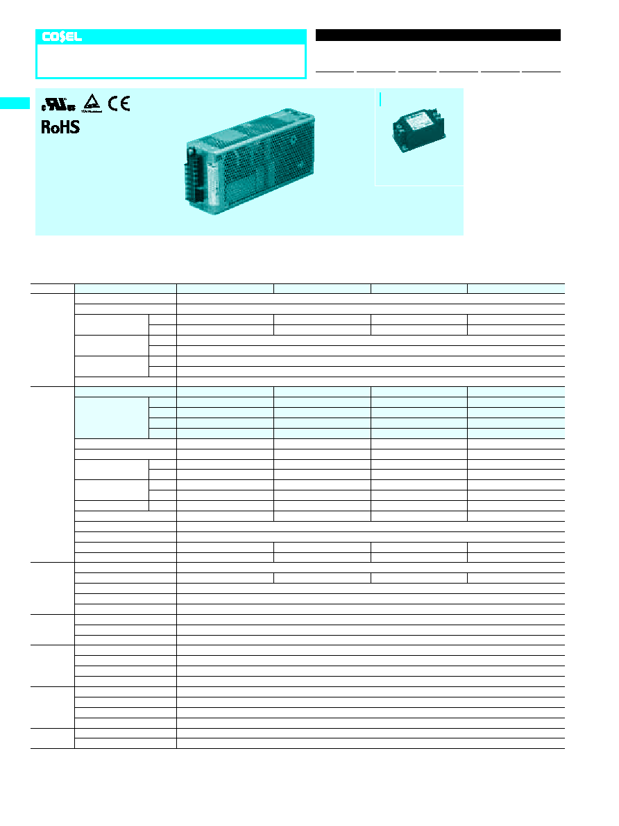
ADA600F-24
ADA600F-30
ADA600F-36
ADA600F-48
INPUT
VOLTAGE[V]
AC85 - 264 1
f
or DC 120 - 350 (AC64 or DC90 optionally available
*
6)
FREQUENCY[Hz]
50/60 (47 - 63) or DC
EFFICIENCY[%]
ACIN 100V 84typ (Io=100%)
86typ (Io=100%)
86typ (Io=100%)
86typ (Io=100%)
ACIN 200V 86typ (Io=100%)
87typ (Io=100%)
87typ (Io=100%)
89typ (Io=100%)
POWER FACTOR
ACIN 100V 0.99typ (Io=100%)
ACIN 200V 0.98typ (Io=100%)
INRUSH CURRENT[A]
ACIN 100V
*
1
20typ (Io=100%) (More than 3sec.to re-start)
ACIN 200V
*
1
40typ (Io=100%) (More than 3sec.to re-start)
LEAKAGE CURRENT[mA]
0.75max (60Hz, According to IEC60950 and DEN-AN) (Io=100%)
OUTPUT
VOLTAGE[V]
24
30
36
48
CURRENT[A]
ACIN 100V
*
2
14 (Peak 25) convection
11 (Peak 20) convection
9 (Peak 16.5) convection
6.5 (Peak 12.5) convection
ACIN 100V
*
2
21 (Peak 25) forced air
16.5 (Peak 20) forced air
14 (Peak 16.5) forced air
10.5 (Peak 12.5) forced air
ACIN 200V
*
2
15 (Peak 31) convection
12 (Peak 24.5) convection
10 (Peak 20.5) convection
7 (Peak 15.5) convection
ACIN 200V
*
2
25 (Peak 31) forced air
20 (Peak 24.5) forced air
16.5 (Peak 20.5) forced air
12.5 (Peak 15.5) forced air
LINE REGULATION[mV]
96max
120max
144max
192max
LOAD REGULATION[mV]
150max
180max
240max
300max
RIPPLE[mVp-p]
0 to +50
C
*
3
120max
160max
200max
200max
-10 - 0
C
*
3
160max
230max
260max
300max
RIPPLE NOISE[mVp-p]
0 to +50
C
*
3
150max
190max
230max
250max
-10 - 0
C
*
3
180max
250max
280max
400max
TEMPERATURE REGULATION[mV] 0 to +50
C
240max
300max
360max
480max
DRIFT[mV]
*
4
96max
120max
144max
192max
START-UP TIME[ms]
500max (ACIN 100V, Io=100%)
HOLD-UP TIME[ms]
20typ (ACIN 100V, Io=100%)
OUTPUT VOLTAGE ADJUSTMENT RANGE[V] 21.6 - 27.0
27.0 - 33.0
33.0 - 41.0
41.0 - 52.8
OUTPUT VOLTAGE SETTING[V]
23.5 - 24.5
29.0 - 31.0
35.0 - 37.0
47.0 - 49.0
PROTECTION
CIRCUIT AND
OTHERS
OVERCURRENT PROTECTION Works over 101% of peak current and recovers automatically
OVERVOLTAGE PROTECTION[V]
31 - 34.5
40 - 48
51 - 60
64 - 76
OPERATING INDICATION
LED (Green)
ALARM OUTPUT
Detecting low input voltage(PF), detecting low output voltage(LV). (Optional : -W, refer to Instruction Manual 5)
REMOTE ON/OFF(RC)
Requirement for external source (Option : -R, refer to Instruction Manual 5)
ISOLATION
INPUT-OUTPUT
-
RC
*
5
AC3,000V 1minute, Cutoff current = 10mA, DC500V 50M
W
min (At Room Temperature)
INPUT-FG
AC2,000V 1minute, Cutoff current = 10mA, DC500V 50M
W
min (At Room Temperature)
OUTPUT
-
RC-FG
*
5
AC500V 1minute, Cutoff current = 100mA, DC500V 50M
W
min (At Room Temperature)
ENVIRONMENT
OPERATING TEMP.,HUMID.AND ALTITUDE -10 to +71
C
, 20 - 90%RH (Non condensing) (Refer to DERATING CURVE), 3,000m (10,000feet) max
STORAGE TEMP.,HUMID.AND ALTITUDE -20 to +75
C
, 20 - 90%RH (Non condensing), 9,000m (30,000feet) max
VIBRATION
10 - 55Hz, 19.6m/s
2
(2G), 3minutes period, 60minutes each along X, Y and Z axis
IMPACT
196.1m/s
2
(20G), 11ms, once each X, Y and Z axis
SAFETY AND
NOISE
REGULATIONS
AGENCY APPROVALS
UL60950-1, C-UL(CSA60950-1), EN60950-1, EN50178 Complies with DEN-AN and IEC60950-1 (At only AC input)
CONDUCTED NOISE
Complies with FCC-B, CISPR22-B, EN55022-B, VCCI-B
CE MARKING
Low Voltage Directive, EMC Directive
HARMONIC ATTENUATOR
Complies with IEC61000-3-2
OTHERS
CASE SIZE/WEIGHT
65
X
127
X
195mm (W
X
H
X
D) (without terminal block) /1.5kg max
COOLING METHOD
Convection/Forced air
*
1
The value is primary surge.The current of input surge to a built-in noise filter (0.2ms or less) is
excluded.
*
2
Peak loading for 10sec.And Duty 35% max.Refer to Instruction Manual 4.Forced air is shown
in Instruction Manual 2.3.
*
3
This is the value that measured on measuring board with capacitor of 22
m
F within 150mm
from output terminal.Measured by 20MHz oscilloscope or Ripple-Noise meter (Equivalent to
KEISOKU-GIKEN: RM101).
*
4
Drift is the change in DC output for an eight hour period after a half-hour warm-up at 25
C
,
with the input voltage held constant at the rated input/output.
*
5
Applicable when remote control (optional) is added.
*
6 Derating is required.Consult us for details.
*
A sound may occur from power supply at pulse loading.
ADA600F
Unit type
ADA 600
F
-24
-
O
Ordering information
1
Series name
2
Output wattage
3
Universal input
4
Output voltage
5
Optional
G :Low leakage current
E :Low leakage current
and EMI class A
F :with Fan unit(only -24)
T :Vertical terminal block
J :Connector type
C :with Coating
R :Remote ON/OFF
N1:DIN rail
W:Alarms and Redundant
operation
Specification is changed at
option,refer to Instruction
Manual.
R
1
2
3
4
5
ADA
A-120
Please refer to derating curve, because the rated load current depends on cooling method that is convention cooling or forced air.
Recommended Noise Filter
NAC-20-472
High voltage pulse noise type : NAP series
Low leakage current type : NAM series
*The Noise Filter is recommended
*
to connect with several devices.
6
7
14 13
12
10
8
4
11
9
5
3
2
1
Mounting hole
PF Alarm ground(-W)
:
PF-
PF Alarm(-W)
:
PF+
N.C.
:
NC
LV Alarm ground(-W)
:
LV-
:
LV+
LV Alarm(-W)
Remote ON/OFF-(-R)
:
NC
N.C.
CN3(Option)
Terminal
Mfr.
J.S.T
Mating connector
Connector
Loose:BPHD-001T-P0.5
Chain:SPHD-002T-P0.5
PHDR-14VS
S14B-PHDSS
CN3
CN3(Option)
8-M4
Mounting hole
(Both sides)
Average 21A max per pin for TB1
Screw type
M4
M3
�
Chassis and cover material : aluminium
M4 : 1.6N
�
m(16.9kgf
�
cm) max , M3 : 0.8N
�
m(8.5kgf
�
cm) max
�
Weight : 1.5kg max
�
PCB material / thickness : FR-4 / 1.6mm
�
Dimensions in mm
�
Mounting torque : 1.2N
�
m(12.8kgf
�
cm) max
�
Screw tighting torque
�
I/0 terminal for option-J and -T is shown in Instruction Manual 5.
�
Tolerance :
�
1
Symbol
Function
VB
Voltage balance
CB
Current balance
+V
+V
-V
-V
FG
N
L
Output terminal(+)
Output terminal(+)
Output terminal(-)
Output terminal(-)
Frame ground
AC(N)
AC(L)
�
Pin assign
4-M4
Mounting hole
(Bottom)
2-M4
Mounting hole
Terminal cover
L
N
FG
-V
-V
+V
+V
CB
VB
TB1
Voltage adjust
LED
Name plate
2-M4
Pin No.
Function
1
2
3-8
9
10
11-12
13
14
:
RC+
Remote ON/OFF+(-R)
:
RC-
48
195
65
26.5
29
�
0.5
9
(19)
6.6
10
9
8
27.5
8.6
13
(22.6)
16.2
9
18
130.5
�
0.5
35
�
0.5
29
114.5
127
105
�
0.5
11
48
20
18.1
130.5
�
0.5
BPHD-002T-P0.5
*
1
Ratchet Hand is nothing
*
1
M3.5
FG hole
ADA
A-121
ADA600F
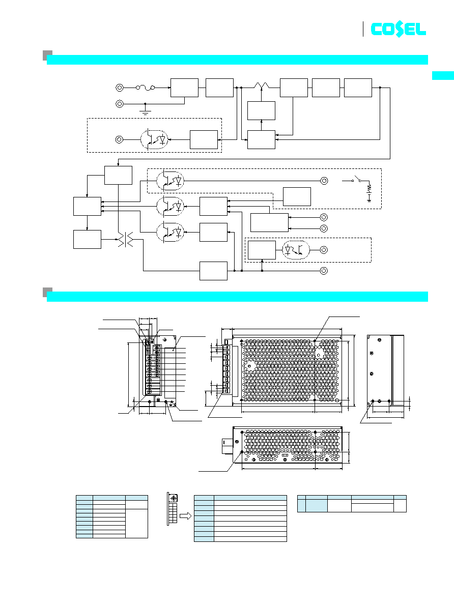
Block diagram
250V12A
FG
PF alarm
(-W)
filter
Alarm
circuit
Rectifier
&
Smooth
Inrush
current
limitting
Control
Control
protection
Over voltage
output voltage
Detecting
circuit
Master-Slave
DC OUT
Noise
current
Detecting
Rectifier
&
Smooth
Inverter
AC IN 85 - 264V
Fuse
Rectifier
Booster inductor
Inverter
Control
Detecting
current
N+1
Redundancy
RC
External source
Option
Option
Option
(-R)
Current Balance (CB)
Voltage Balance (VB)
LV alarm (-W)
(-W)
External view
SPECIFICATIONS
MODEL
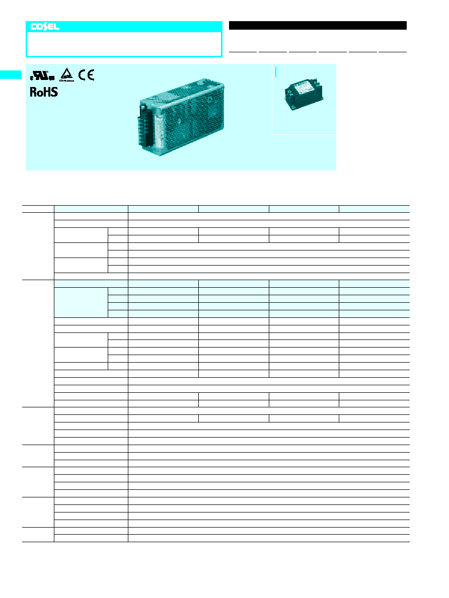
ADA750F-24
ADA750F-30
ADA750F-36
ADA750F-48
INPUT
VOLTAGE[V]
AC85 - 264 1
f
or DC 120 - 350 (AC64 or DC90 optionally available
*
6)
FREQUENCY[Hz]
50/60 (47 - 63) or DC
EFFICIENCY[%]
ACIN 100V 86typ (Io=100%)
86typ (Io=100%)
87typ (Io=100%)
87typ (Io=100%)
ACIN 200V 88typ (Io=100%)
88typ (Io=100%)
89typ (Io=100%)
89typ (Io=100%)
POWER FACTOR
ACIN 100V 0.99typ (Io=100%)
ACIN 200V 0.98typ (Io=100%)
INRUSH CURRENT[A]
ACIN 100V
*
1
20typ (Io=100%) (More than 3sec.to re-start)
ACIN 200V
*
1
40typ (Io=100%) (More than 3sec.to re-start)
LEAKAGE CURRENT[mA]
0.75max (60Hz, According to IEC60950 and DEN-AN) (Io=100%)
OUTPUT
VOLTAGE[V]
24
30
36
48
CURRENT[A]
ACIN 100V
*
2
17 (Peak 42) convection
13.5 (Peak 33.5) convection 11 (Peak 28) convection
8 (Peak 21) convection
ACIN 100V
*
2
25 (Peak 42) forced air
20 (Peak 33.5) forced air
16.5 (Peak 28) forced air
12.5 (Peak 21) forced air
ACIN 200V
*
2
19 (Peak 63) convection
15 (Peak 50) convection
12.5 (Peak 42) convection
9 (Peak 31.5) convection
ACIN 200V
*
2
31.5 (Peak 63) forced air
24.5 (Peak 50) forced air
20.5 (Peak 42) forced air
15.5 (Peak 31.5) forced air
LINE REGULATION[mV]
96max
120max
144max
192max
LOAD REGULATION[mV]
150max
180max
240max
300max
RIPPLE[mVp-p]
0 to +50
C
*
3
120max
160max
200max
200max
-10 - 0
C
*
3
160max
230max
260max
300max
RIPPLE NOISE[mVp-p]
0 to +50
C
*
3
150max
190max
230max
250max
-10 - 0
C
*
3
180max
250max
280max
400max
TEMPERATURE REGULATION[mV] 0 to +50
C
240max
300max
360max
480max
DRIFT[mV]
*
4
96max
120max
144max
192max
START-UP TIME[ms]
500max (ACIN 100V, Io=100%)
HOLD-UP TIME[ms]
20typ (ACIN 100V, Io=100%)
OUTPUT VOLTAGE ADJUSTMENT RANGE[V] 21.6 - 27.0
27.0 - 33.0
33.0 - 41.0
41.0 - 52.8
OUTPUT VOLTAGE SETTING[V]
23.5 - 24.5
29.0 - 31.0
35.0 - 37.0
47.0 - 49.0
PROTECTION
CIRCUIT AND
OTHERS
OVERCURRENT PROTECTION Works over 101% of peak current and recovers automatically
OVERVOLTAGE PROTECTION[V]
31 - 34.5
40 - 48
51 - 60
64 - 76
OPERATING INDICATION
LED (Green)
ALARM OUTPUT
Detecting low input voltage(PF), detecting low output voltage(LV). (Optional : -W, refer to Instruction Manual 5)
REMOTE ON/OFF(RC)
Requirement for external source (Option : -R, refer to Instruction Manual 5)
ISOLATION
INPUT-OUTPUT
-
RC
*
5
AC3,000V 1minute, Cutoff current = 10mA, DC500V 50M
W
min (At Room Temperature)
INPUT-FG
AC2,000V 1minute, Cutoff current = 10mA, DC500V 50M
W
min (At Room Temperature)
OUTPUT
-
RC-FG
*
5
AC500V 1minute, Cutoff current = 100mA, DC500V 50M
W
min (At Room Temperature)
ENVIRONMENT
OPERATING TEMP.,HUMID.AND ALTITUDE -10 to +71
C
, 20 - 90%RH (Non condensing) (Refer to DERATING CURVE), 3,000m (10,000feet) max
STORAGE TEMP.,HUMID.AND ALTITUDE -20 to +75
C
, 20 - 90%RH (Non condensing), 9,000m (30,000feet) max
VIBRATION
10 - 55Hz, 19.6m/s
2
(2G), 3minutes period, 60minutes each along X, Y and Z axis
IMPACT
196.1m/s
2
(20G), 11ms, once each X, Y and Z axis
SAFETY AND
NOISE
REGULATIONS
AGENCY APPROVALS
UL60950-1, C-UL(CSA60950-1), EN60950-1, EN50178 Complies with DEN-AN and IEC60950-1 (At only AC input)
CONDUCTED NOISE
Complies with FCC-B, CISPR22-B, EN55022-B, VCCI-B
CE MARKING
Low Voltage Directive, EMC Directive
HARMONIC ATTENUATOR
Complies with IEC61000-3-2
OTHERS
CASE SIZE/WEIGHT
70
X
127
X
230mm (W
X
H
X
D) (without terminal block) /1.9kg max
COOLING METHOD
Convection/Forced air
*
1
The value is primary surge.The current of input surge to a built-in noise filter (0.2ms or less) is
excluded.
*
2
Peak loading for 10sec.And Duty 35% max.Refer to Instruction Manual 4.Forced air is shown
in Instruction Manual 2.3.
*
3
This is the value that measured on measuring board with capacitor of 22
m
F within 150mm
from output terminal.Measured by 20MHz oscilloscope or Ripple-Noise meter (Equivalent to
KEISOKU-GIKEN: RM101).
*
4
Drift is the change in DC output for an eight hour period after a half-hour warm-up at 25
C
,
with the input voltage held constant at the rated input/output.
*
5
Applicable when remote control (optional) is added.
*
6 Derating is required.Consult us for details.
*
A sound may occur from power supply at pulse loading.
ADA750F
Unit type
ADA 750
F
-24
-
O
Ordering information
1
Series name
2
Output wattage
3
Universal input
4
Output voltage
5
Optional
G :Low leakage current
E :Low leakage current
and EMI class A
F :with Fan unit(only -24)
T :Vertical terminal block
J :Connector type
C :with Coating
R :Remote ON/OFF
N1:DIN rail
W:Alarms and Redundant
operation
Specification is changed at
option,refer to Instruction
Manual.
R
1
2
3
4
5
ADA
A-122
Please refer to derating curve, because the rated load current depends on cooling method that is convention cooling or forced air.
Recommended Noise Filter
NAC-20-472
High voltage pulse noise type : NAP series
Low leakage current type : NAM series
*The Noise Filter is recommended
*
to connect with several devices.
Mfr.
J.S.T
*
1
Ratchet Hand is nothing
*
1
-V
FG
N
L
TB1
Terminal cover
Name plate
2-M4
Mounting hole
Voltage adjust
8-M4
Mounting hole
(Both sides)
4-M4
Mounting hole
(Bottom)
2-M4
Mounting hole
LED
-V
+V
+V
CB
VB
CN3(Option)
6
14
12
10
8
4
2
7
13
11
9
5
3
1
9
13
18
29
114.5
18.1
(22.6)
30.5
29
�
0.5
(19)
16.2
27.5
8
9
10
6.6
8.6
9
175.5
�
0.5
38
35
�
0.5
20
230
127
70
11
38
105
�
0.5
175.5
�
0.5
PF Alarm ground(-W)
:
PF-
PF Alarm(-W)
:
PF+
N.C.
:
NC
LV Alarm ground(-W)
:
LV-
:
LV+
LV Alarm(-W)
Remote ON/OFF-(-R)
:
NC
N.C.
CN3(Option)
Average 21A max per pin for TB1
M4
M3
�
Chassis and cover material : aluminium
M4 : 1.6N
�
m(16.9kgf
�
cm) max , M3 : 0.8N
�
m(8.5kgf
�
cm) max
�
Weight : 1.9kg max
�
PCB material / thickness : FR-4 / 1.6mm
�
Dimensions in mm
�
Mounting torque : 1.2N
�
m(12.8kgf
�
cm) max
�
Screw tighting torque
�
I/0 terminal for option-J and -T is shown in Instruction Manual 5.
�
Tolerance :
�
1
VB
Voltage balance
CB
Current balance
+V
+V
-V
-V
FG
N
L
Output terminal(+)
Output terminal(+)
Output terminal(-)
Output terminal(-)
Frame ground
AC(N)
AC(L)
�
Pin assign
Pin No.
Function
1
2
3-8
9
10
11-12
13
14
:
RC+
Remote ON/OFF+(-R)
:
RC-
Screw type
Symbol
Function
Terminal
Mating connector
Connector
Loose:BPHD-001T-P0.5
BPHD-002T-P0.5
Chain:SPHD-002T-P0.5
PHDR-14VS
S14B-PHDSS
CN3
M3.5
FG hole
ADA
A-123
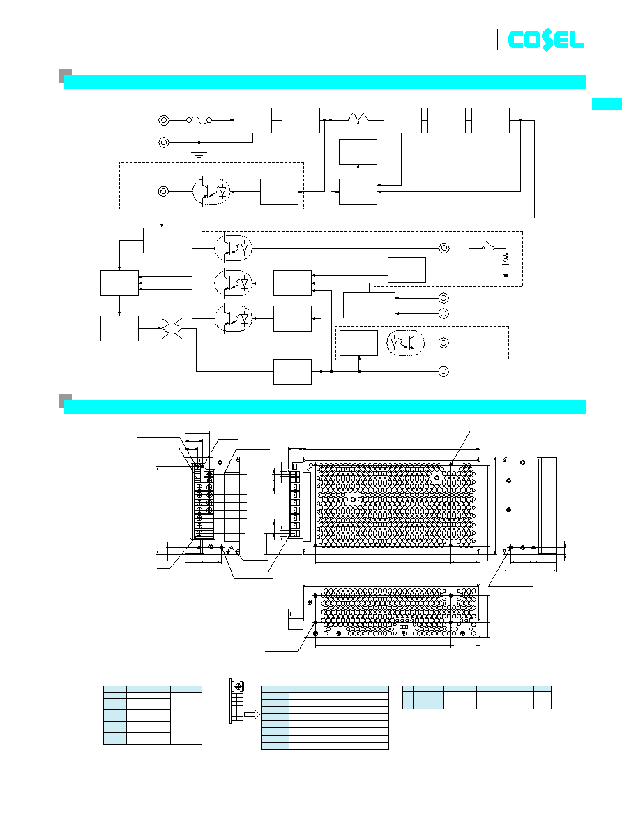
ADA750F
Block diagram
250V20A
FG
PF alarm
(-W)
filter
Alarm
circuit
Rectifier
&
Smooth
Inrush
current
limitting
Control
Control
protection
Over voltage
output voltage
Detecting
circuit
Master-Slave
DC OUT
Noise
current
Detecting
Rectifier
&
Smooth
Inverter
AC IN 85 - 264V
Fuse
Rectifier
Booster inductor
Inverter
Control
Detecting
current
N+1
Redundancy
RC
External source
Option
Option
Option
(-R)
Current Balance (CB)
Voltage Balance (VB)
LV alarm (-W)
(-W)
External view
SPECIFICATIONS
MODEL
ADA1000F-24
ADA1000F-30
ADA1000F-36
ADA1000F-48
INPUT
VOLTAGE[V]
AC85 - 264 1
f
or DC 120 - 350 (AC64 or DC90 optionally available
*
6)
FREQUENCY[Hz]
50/60 (47 - 63) or DC
EFFICIENCY[%]
ACIN 100V 86typ (Io=100%)
86typ (Io=100%)
87typ (Io=100%)
87typ (Io=100%)
ACIN 200V 88typ (Io=100%)
88typ (Io=100%)
89typ (Io=100%)
89typ (Io=100%)
POWER FACTOR
ACIN 100V 0.99typ (Io=100%)
ACIN 200V 0.98typ (Io=100%)
INRUSH CURRENT[A]
ACIN 100V
*
1
20typ (Io=100%) (More than 3sec.to re-start)
ACIN 200V
*
1
40typ (Io=100%) (More than 3sec.to re-start)
LEAKAGE CURRENT[mA]
0.75max (60Hz, According to IEC60950 and DEN-AN) (Io=100%)
OUTPUT
VOLTAGE[V]
24
30
36
48
CURRENT[A]
ACIN 100V
*
2
21 (Peak 63) convection
16.5 (Peak 50) convection
14 (Peak 42) convection
10.5 (Peak 31.5) convection
ACIN 100V
*
2
33 (Peak 63) forced air
26 (Peak 50) forced air
22 (Peak 42) forced air
16.5 (Peak 31.5) forced air
ACIN 200V
*
2
25 (Peak 83) convection
20 (Peak 66) convection
16.5 (Peak 55) convection
11.5 (Peak 41.5) convection
ACIN 200V
*
2
42 (Peak 83) forced air
33.5 (Peak 66) forced air
28 (Peak 55) forced air
21 (Peak 41.5) forced air
LINE REGULATION[mV]
96max
120max
144max
192max
LOAD REGULATION[mV]
150max
180max
240max
300max
RIPPLE[mVp-p]
0 to +50
C
*
3
120max
160max
200max
200max
-10 - 0
C
*
3
160max
230max
260max
300max
RIPPLE NOISE[mVp-p]
0 to +50
C
*
3
150max
190max
230max
250max
-10 - 0
C
*
3
180max
250max
280max
400max
TEMPERATURE REGULATION[mV] 0 to +50
C
240max
300max
360max
480max
DRIFT[mV]
*
4
96max
120max
144max
192max
START-UP TIME[ms]
500max (ACIN 100V, Io=100%)
HOLD-UP TIME[ms]
20typ (ACIN 100V, Io=100%)
OUTPUT VOLTAGE ADJUSTMENT RANGE[V] 21.6 - 27.0
27.0 - 33.0
33.0 - 41.0
41.0 - 52.8
OUTPUT VOLTAGE SETTING[V]
23.5 - 24.5
29.0 - 31.0
35.0 - 37.0
47 - 49
PROTECTION
CIRCUIT AND
OTHERS
OVERCURRENT PROTECTION Works over 101% of peak current and recovers automatically
OVERVOLTAGE PROTECTION[V]
31 - 34.5
40 - 48
51 - 60
64 - 76
OPERATING INDICATION
LED (Green)
ALARM OUTPUT
Detecting low input voltage(PF), detecting low output voltage(LV). (Optional : -W, refer to Instruction Manual 5)
REMOTE ON/OFF(RC)
Requirement for external source (Option : -R, refer to Instruction Manual 5)
ISOLATION
INPUT-OUTPUT
-
RC
*
5
AC3,000V 1minute, Cutoff current = 10mA, DC500V 50M
W
min (At Room Temperature)
INPUT-FG
AC2,000V 1minute, Cutoff current = 10mA, DC500V 50M
W
min (At Room Temperature)
OUTPUT
-
RC-FG
*
5
AC500V 1minute, Cutoff current = 100mA, DC500V 50M
W
min (At Room Temperature)
ENVIRONMENT
OPERATING TEMP.,HUMID.AND ALTITUDE -10 to +71
C
, 20 - 90%RH (Non condensing) (Refer to DERATING CURVE), 3,000m (10,000feet) max
STORAGE TEMP.,HUMID.AND ALTITUDE -20 to +75
C
, 20 - 90%RH (Non condensing), 9,000m (30,000feet) max
VIBRATION
10 - 55Hz, 19.6m/s
2
(2G), 3minutes period, 60minutes each along X, Y and Z axis
IMPACT
196.1m/s
2
(20G), 11ms, once each X, Y and Z axis
SAFETY AND
NOISE
REGULATIONS
AGENCY APPROVALS
UL60950-1, C-UL(CSA60950-1), EN60950-1, EN50178 Complies with DEN-AN and IEC60950-1 (At only AC input)
CONDUCTED NOISE
Complies with FCC-B, CISPR22-B, EN55022-B, VCCI-B
CE MARKING
Low Voltage Directive, EMC Directive
HARMONIC ATTENUATOR
Complies with IEC61000-3-2
OTHERS
CASE SIZE/WEIGHT
75
X
127
X
280mm (W
X
H
X
D) (without terminal block) /2.5kg max
COOLING METHOD
Convection/Forced air
*
1
The value is primary surge.The current of input surge to a built-in noise filter (0.2ms or less) is
excluded.
*
2
Peak loading for 10sec.And Duty 35% max.Refer to Instruction Manual 4.Forced air is shown
in Instruction Manual 2.3.
*
3
This is the value that measured on measuring board with capacitor of 22
m
F within 150mm
from output terminal.Measured by 20MHz oscilloscope or Ripple-Noise meter (Equivalent to
KEISOKU-GIKEN: RM101).
*
4
Drift is the change in DC output for an eight hour period after a half-hour warm-up at 25
C
,
with the input voltage held constant at the rated input/output.
*
5
Applicable when remote control (optional) is added.
*
6 Derating is required.Consult us for details.
*
A sound may occur from power supply at pulse loading.
ADA1000F
Unit type
ADA 1000
F
-24
-
O
Ordering information
1
Series name
2
Output wattage
3
Universal input
4
Output voltage
5
Optional
G :Low leakage current
E :Low leakage current
and EMI class A
F :with Fan unit(only -24)
T :Vertical terminal block
J :Connector type
C :with Coating
R :Remote ON/OFF
N1:DIN rail
W:Alarms and Redundant
operation
Specification is changed at
option,refer to Instruction
Manual.
R
1
2
3
4
5
ADA
A-124
Please refer to derating curve, because the rated load current depends on cooling method that is convention cooling or forced air.
Recommended Noise Filter
NAC-20-472
High voltage pulse noise type : NAP series
Low leakage current type : NAM series
*The Noise Filter is recommended
*
to connect with several devices.
RoHS : Please consult us for details