 | –≠–ª–µ–∫—Ç—Ä–æ–Ω–Ω—ã–π –∫–æ–º–ø–æ–Ω–µ–Ω—Ç: RT1400B6 | –°–∫–∞—á–∞—Ç—å:  PDF PDF  ZIP ZIP |
© 2006 CTS Corporation. All rights reserved. Information subject to change.
CTS Electronic Components
Page 1
July 06
www.ctscorp.com
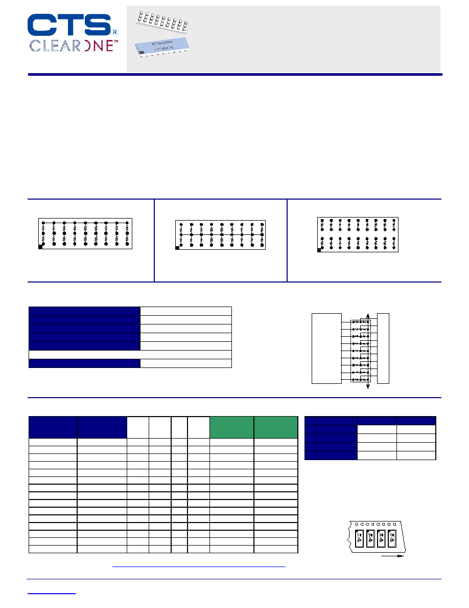
DDR SDRAM Terminator
Electrical Specifications
Resistor Tolerance:
±
1.0%
TCR
±
200ppm/
∞
C
Operating Temperature Range
-55
∞
C to +125
∞
C
Maximum Resistor Power:
0.05 Watts at 70
∞
C
Maximum Package Power:
1.0 Watts at 70
∞
C
Process Requirements:
Maximum Re-flow Temperature
Per IPC/JEDEC J-STD-020C
Typical Application
Memory
Controller
DIMM
RT2400
VTT
VTT
Features
∑
18 Bit SSTL_2 Termination Sets
∑
Compliant to JEDEC Std. 8-9A
∑
Excellent high frequency performance
∑
Slim BGA Package
∑
1% Resistor Tolerance
∑
Low Channel Capacitance
∑
RoHS Compliant Designs Available
∑
Compatible with both lead and lead-free
manufacturing processes
Ordering Information
1.27mm Pitch
Standard Part
No.
1.00mm Pitch
Standard
Part No.
Style R1
R2
Array
Size
1.27mm Pitch
RoHS Part No.
1.00mm Pitch
RoHS Part No.
RT1400B6
*
RT1400B7
*
H
50
25
3 x 9
RT2400B6
*
RT2400B7
*
RT1401B6
RT1401B7
H
25
22
3 x 9
RT2401B6
RT2401B7
RT1402B6
*
RT1402B7
*
F
50
-
3 x 9
RT2402B6
*
RT2402B7
*
RT1403B6
*
RT1403B7
*
F
25
-
3 x 9
RT2403B6
*
RT2403B7
*
RT1404B6
*
RT1404B7
*
C
25
-
4 x 9
RT2404B6
*
RT2404B7
*
RT1405B6
*
RT1405B7
*
C
22
-
4 x 9
RT2405B6
*
RT2405B7
*
RT1407B6
*
RT1407B7
*
F
35
-
3 x 9
RT2407B6
*
RT2407B7
*
RT1408B6
*
RT1408B7
*
H
60
25
3 x 9
RT2408B6
*
RT2408B7
*
RT1430B6
RT1430B7
F
60
-
3 x 9
RT2430B6
RT2430B7
RT1432B6
RT1432B7
F
120
-
3 x 9
RT2432B6
RT2432B7
RT1460B6
RT1460B7
C
50
-
4 x 9
RT2460B6
RT2460B7
RT1463B6
*
RT1463B7
C
33
-
4 x 9
RT2463B6
*
RT2463B7
RT1465B6
RT1465B7
C
47
-
4 x 9
RT2465B6
RT2465B7
RT1467B6
*
RT1467B7
*
F
75
-
3 x 9
RT2467B6
*
RT2467B7
*
RT1468B6
*
RT1468B7
*
F
150
-
3 x 9
RT2468B6
*
RT2468B7
*
*Indicates available Top Probe-able part numbers.
Refer to the following link for detailed Top
Side Probe-able information:
www.ctscorp.com/components/clearone/TopProveClearOne.pdf
Description
This SSTL_2 terminator network provides high performance
resistor termination for SSTL_2 Class I or Class II systems.
Designed with a ceramic substrate, this device minimizes
channel capacitance, a primary cause of reduced system
performance. In addition, the BGA package eases routing
design, saving the designer many hours of printed circuit
layout.
The BGA packaging has been proven to reduce rework and
improve reliability.
R1
R2
D
E
F
A
B
C
G
H
1
2
3
J
DDR SDRAM Terminator
Technical
Data Sheet
RoHS Compliant Parts Available
D
E
F
A
B
C
G
H
J
1
2
3
D
E
F
A
B
C
G
H
J
1
2
4
3
Style H
Style F
Style C
R1
R1
R1
R1
Packaging Information
Suffix
TR7
TR13
Tape Width
24 mm
24mm
Carrier Pitch
8 mm
8 mm
Reel Diameter
7 inch
13 inch
Parts/Reel
1,000 4,000
Part Number Coding
7 inch reel, Add TR7 to part
number, example RT2400B6TR7
13 inch reel, Add TR13 to part
number, example RT2400B6TR13
(Bulk packaging is not available)
Direction of Feed

© 2006 CTS Corporation. All rights reserved. Information subject to change.
CTS Electronic Components
Page 2
July 06
www.ctscorp.com
DDR SDRAM Terminator
BGA Routing Scheme
Recommended Land Pattern
1.00mm Pitch (B7) = 0.51mm/.020 inch (minimum)
1.27mm pitch (B6) = 0.64mm/.025 inch (minimum)
Outline of Substrate
PCB Pad Diameter
For .006" Thick Solder Paste Stencil, Aperture Opening Should
be Equal to the PCB Pad Diameter.
Refer to
www.ctscorp.com/components/clearone.asp
for
additional PCB design information
Solder Mask Dia = Pad
Diameter +.15mm (.006 inch)
.005 Inch
Wide Traces
1.00 mm Pitch Package
1.27 mm Pitch Package
RT2402B7
RT2402B6
RT2404B6
RT2404B7
.008" Trace Width to
VTT Island
.010" Trace Width to
VTT Island
.005 Inch
Wide Traces
Mechanical Diagrams
K
P (Pitch)
D
L
W
H
P (Pitch)
A1 Identifier
RT_40_B_
CTS YRWK
1.27mm Pitch
L
W
H
P
D
K
mm
11.43
±
0.15 3.81
±
0.15 1.32
±
0.15 1.27
±
0.25 0.76
±
0.05 0.64
±
0.25
Styles
H & F
inch
.450
±
.006 .150
±
.006 .052
±
.006 .050
±
.010 .030
±
.002 .025
±
.010
1.0mm Pitch
L
W
H
P
D
K
mm
9.00
±
0.15 3.00
±
0.15 1.19
±
0.15 1.00
±
0.25 0.64
±
0.05 0.50
±
0.25
Styles
H & F
inch
.354
±
.006 .118
±
.006 .047
±
.006 .039
±
.010 .025
±
.002 .020
±
.010
K
P (Pitch)
L
W
H
P (Pitch)
A1 Identifier
RT_40_B_
CTS YRWK
D
1.27mm Pitch
L
W
H
P
D
K
mm
11.43
±
0.15 5.08
±
0.15 1.32
±
0.15 1.27
±
0.25 0.76
±
0.05 0.64
±
0.25
Style C
inch
.450
±
.006 .200
±
.006 .052
±
.006 .050
±
.010 .030
±
.002 .025
±
.010
1.0mm Pitch
L
W
H
P
D
K
mm
9.00
±
0.15 4.00
±
0.15 1.19
±
0.15 1.00
±
0.25 0.64
±
0.05 0.50
±
0.25
Style C
inch
.354
±
.006 .157
±
.006 .047
±
.006 .039
±
.010 .025
±
.002 .020
±
.010
© 2006 CTS Corporation. All rights reserved. Information subject to change.
CTS Electronic Components
Page 3
July 06
www.ctscorp.com
DDR SDRAM Terminator
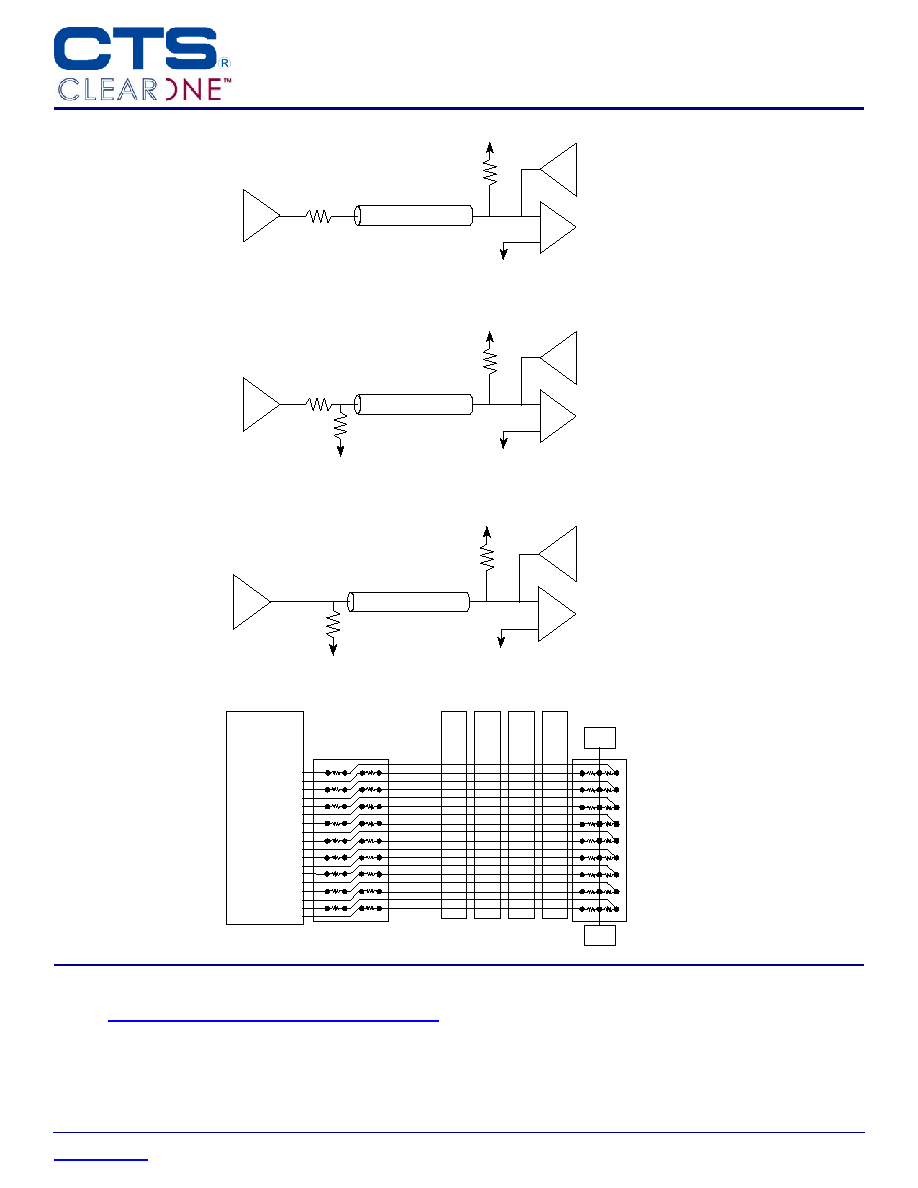
Applications
Complete ClearONE Product, Processing, and Application Information can be found at the following link:
http://www.ctscorp.com/components/clearone.asp
This product is covered by one or more of the following U.S. and foreign patents:
US 5,977,863; TW 133,148; US 6,005,777; US 6,194,979; TW 89104035; US 6,097,277; US 6,246,312; US 6,749,775; US 6,577,225; US 6,963,265;
US 6,897,761; US 6,882,266; US 6,946,733; US 6,856,516. Other U.S. and foreign patents pending.
DIMM
Memory Controller
D0
LDQS
D15
UDQS
DIMM
DIMM
DIMM
VTT
VTT
RT2404
RT2402
DDR SDRAM SSTL_2
ith
Single End Termination.
SSTL_2
Vout
VTT = 0.5V x V
DDQ
VREF = 0.5V x V
DDQ
VIN
RS = 25 ohms
1/18 RT2404
RT = 50 ohms
1/18 RT2402
SSTL_2 Class I, symmetrically
single
parallel terminated output
load, and series resistor.
SSTL_2
Vout
VTT = 0.5V x V
DDQ
VREF = 0.5V x V
DDQ
VIN
RS = 25 ohms
1/9 RT2400
(R2)
RT2 = 50 ohms
1/18 RT2402
VTT = 0.5V x V
DDQ
SSTL_2 Class II, symmetrically
double
parallel terminated output
load, and series resistor.
RT1 = 50 ohms
1/9 RT2400 (R1)
SSTL_2
Vout
VTT = 0.5V x V
DDQ
VREF = 0.5V x V
DDQ
VIN
RT = 50 ohms
1/18 RT2402
VTT = 0.5V x V
DDQ
SSTL_2 Class I, symmetrically
double parallel terminated output.
RT = 50 ohms
1/18 RT2402