© 2006 CTS Corporation. All rights reserved. Information subject to change
CTS Electronic Components
Page 1
March 06
www.ctscorp.com
VME64 & VME64x Terminators
VME64, VME64x Terminator
Technical
Data Sheet
RoHS Compliant Parts Available
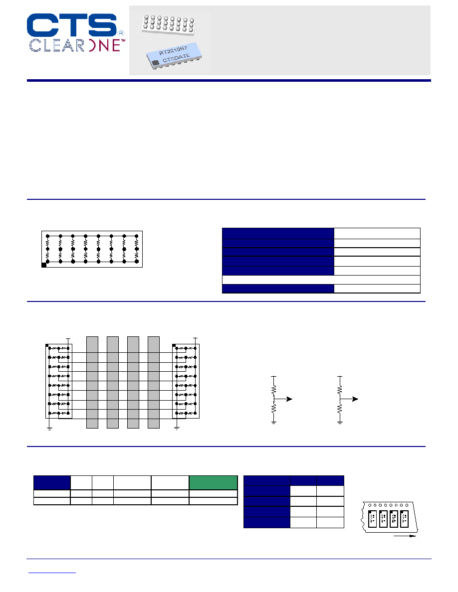
Typical Applications
VME64x Backplane
Card
Card
Card
Card
RT2211
3.3V
RT2211
3.3V
Standard
Termination
VME64
+5V
RT2210
330
Low Voltage
Termination
VME64x
+3.3V
1.8K
220
470
RT2211
Features
∑
8-Bit Termination Network
∑
VME64, VME64x Compliant
∑
Low Channel Capacitance
∑
Laser Trimmed Resistance to ± 1%
∑
Slim BGA Package
∑
RoHS Compliant Designs Available
∑
Compatible with both lead and lead
free processes
Description
This Thevenin termination network provides high performance
resistor termination for VME64 and VME64x back planes.
Designed with a ceramic substrate, this device minimizes
parasitic capacitance and inductance, a primary cause of
reduced system performance. In addition, the BGA package
eases touting design, saving the designer many hours of
printed circuit layout.
The BGA packaging has been proven to reduce rework and
improve reliability
Style G
D
E
F
A
B
C
G
H
1
2
3
R1
R2
Electrical Specifications
Resistor Tolerance:
±
1.0%
TCR
±
200ppm/
∞
C
Operating Temperature Range
-55
∞
C to +125
∞
C
Maximum Resistor Power:
0.05 Watts at 70
∞
C
Maximum Package Power:
1.0 Watts at 70
∞
C
Process Requirements:
Maximum Re-flow Temperature
Per IPC/JEDEC J-STD-020C
Ordering Information
Standard
Part No.
R1
R2
Array Size Pitch (mm)
RoHS
Part No.
RT1210B7
330
470
3 x 8
1.00
RT2210B7
RT1211B7
220
1800
3 x 8
1.00
RT2211B7
Packaging Information
Suffix
TR7
TR13
Tape Width
24 mm
24mm
Carrier Pitch
8 mm
8 mm
Reel Diameter
7 inch
13 inch
Parts/Reel
1,000 4,000
Part Number Coding
7 inch reel, Add TR7 to part
number, example RT2210B7TR7
13 inch reel, Add TR13 to part
number, example RT2210B7TR13
(Bulk packaging is not available)
Direction of Feed

© 2006 CTS Corporation. All rights reserved. Information subject to change
CTS Electronic Components
Page 2
March 06
www.ctscorp.com
VME64 & VME64x Terminators
Complete ClearONE Product, Processing, and Application Information can be found at the following link:
http://www.ctscorp.com/components/clearone.asp
Recommended Land Pattern
1.00 mm Pitch (B7) = 0.51mm/.020 inch
Outline of Substrate
PCB Pad Diameter
For .006" Thick Solder Paste Stencil, Aperture Opening
Should be Equal to the PCB Pad Diameter.
Refer to
www.ctscorp.com/components/clearone.asp
for
additional PCB design information
Blind vias to ground
reference pla ne layer
recommended o n
every oth er row as
shown.
Blind vias to V
CC
reference pla ne layer
recommended o n
every oth er row as
shown.
Blind vias to ground
reference plane layer
recommended on
every other row as
shown.
Vias to Vcc
Termination Island
Solder mask is
used to define
the ball pads.
BGA Routing Schemes
Option A
Option B
Solder Mask Dia = Pad
Diameter +.15mm (.006 inch)
Mechanical Diagram
K
P (Pitch)
L
W
H
P (Pitch)
A1 Identifier
RT_2__B7
CTS YRWK
D
1.0mm Pitch
L
W
H
P
D
K
mm
8.00
±
0.15 3.00
±
0.15 1.19
±
0.15 1.00
±
0.25 0.64
±
0.05 0.50
±
0.25
RT1210B7
RT1211B7
RT2210B7
RT2211B7
inch
.315
±
.006 .157
±
.006 .047
±
.006 .039
±
.010 .025
±
.002 .020
±
.010