
CYNTEC CO., LTD.
DOCUMENT : RLA00000N
REVISION : A2
PAGE : 1 OF 11
1/4W 1220 LOW RESISTNACE CHIP RESISTOR
1. Scope
This specification applies to 2.0mm x 1.25mm size 1/4W, fixed metal film chip resistors rectangular
type for use in electronic equipment.
2. Type Designation
RL1220
- -
N
(1) (2)
(3)
(4)
(5)
Where (1)
Series
No.
(2) Temperature coefficient of resistanceT.C.R.
(3) Resistance value: refer to paragraph 4-1
For example--
Three digits of number ( 0.1
R)
R10 = 0.1
1R0 = 1.0
Four digits of numberR
< 0.1
R022 = 0.022
The "R" shall be used as a decimal point.
(4) Resistance tolerance: refer to paragraph 4-1.
(5) N = Sn plating (Lead free , RoHS compliant)

CYNTEC CO., LTD.
DOCUMENT : RLA00000N
REVISION : A2
PAGE : 2 OF 11
3. Construction and Physical Dimensions
Figure 1-1. Double sides structure (
< 0.082 )
Figure 1-2. Single side structure (
0.082 )
Dimensions (mm)
Code
Letter
Double sides
Structure
Single side
Structure
L
2.00
± 0.20
2.00
± 0.20
W
1.25
± 0.20
1.25
± 0.20
t 0.40
+0.15
-0.10
0.40
± 0.10
a
0.40
± 0.20
0.40
± 0.20
b
0.40
± 0.20
0.40
± 0.20
Note :
Resistive clement
Nickel alloy film
Electrode plating
Sn 100% ( Lead free)
Protective coat
Epoxy Resin coating
Substrate Alumina
ceramic
mass : Double sides structure 5mg (ref.)
Single side structure 4mg (ref.)
b
b
t
L
a
W
a
b
b
t
a
W
a
CYNTEC CO., LTD.
DOCUMENT : RLA00000N
REVISION : A2
PAGE : 3 OF 11
4. Ratings
4-1 Specification
Power Rating*
1/4 W
Resistance Value
10m
18m 22m82m 0.110
Resistance Tolerance
± 5%(J)
± 2%(G) , ± 5%(J)
± 1%(F) , ± 2%(G)
Note*:
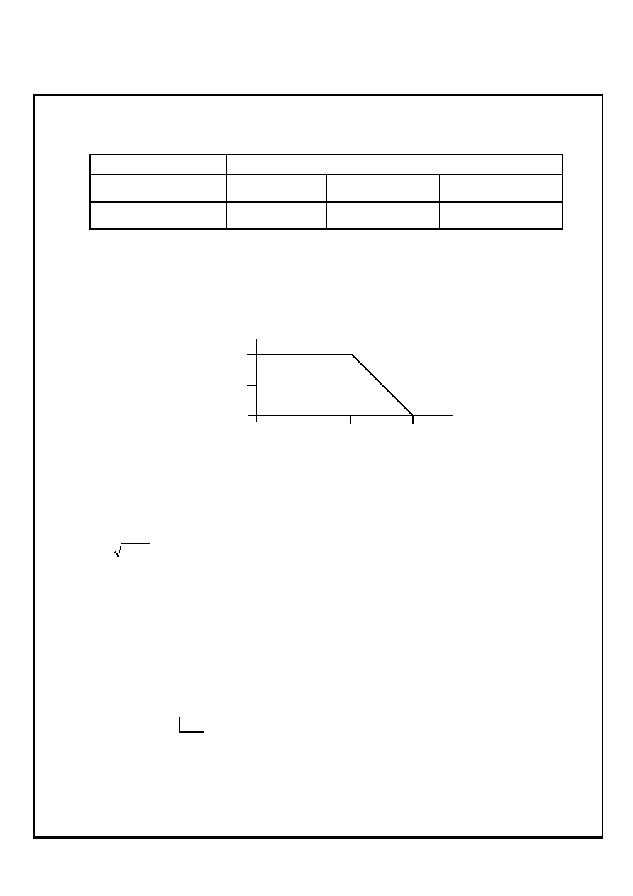
Power Rating is based on continuous full load operation at rated ambient temperature of 70.
For resistors operated at ambient temperature in excess of 70, the maximum load shall be
derated in accordance with the following curve.
Figure 2 Derating Curve
4-2 Rated Voltage
The rated voltage shall be determined by the following expression.
R
P
V
◊
=
Where VRated voltage (V)
RNominal resistance value (
)
PRated dissipation (W)
4-3 Operating and Storage Temperature Range
-55 to +125
5. Marking
A rated resistance shall be marked on the protective coat with three digit of number.
Example ≠ ≠ 0.22
R22
But, there is no marking in the rated resistance under 0.1
-55
0
70
125
100
50
%
Rated
dissipation
ratio
Ambient temperature

CYNTEC CO., LTD.
DOCUMENT : RLA00000N
REVISION : A2
PAGE : 4 OF 11
6. Characteristics
6-1 Electrical
6-1-1 Resistance
Resistance value shall be within the tolerance specified in paragraph 4-1
Refer to IEC 60115-1 Sub-clause 4.5.
6-1-2 Temperature Coefficient of Resistance
Not exceed the temperature coefficient of resistance specified in paragraph 4-1
Room temperature
Room temperature + 100
Refer to IEC 60115-1 Sub-clause 4.13.
6-1-3 Short Time Overload
Resistance Change :
± (0.5%)
Without significant damage by flashover (spark ,arching),burning or breakdown etc.
Test voltage : 2.5 times the rated voltage.
Duration : 5 seconds
Refer to IEC 60115-1 Sub-clause 4.13.
6-1-4 Insulation Resistance
(1) Between Electrode and Protection Film
100M
or over
(2) Between Electrode and Substrate
1,000M
or over
R0.5
Substrate
Protection Film
Pressure Rod
Measurement Point A
(Metal)
Test Sample
Spring
Insulation Prate
Metal Block
Measurement Point B
The resistor shall be cramped in the metal block and tested , as shown below.
Test voltage : 100V
DC
for 1 minute
Refer to IEC 60115-1 Sub-clause 4.6.

CYNTEC CO., LTD.
DOCUMENT : RLA00000N
REVISION : A2
PAGE : 5 OF 11
6-1-5 Voltage Proof
Resistance Change :
± (0.5%)
Without damage by flashover, fire or breakdown, as shown below.
The resistor shall be tested as shown in paragraph 4-1-4
The voltage : 100V
AC
(rms.) for 1 minute
Refer to IEC 60115-1 Sub-clause 4.7.
6-2 Mechanical
6-2-1 Terminal Strength
Resistance Change : ±(0.5%)
Without mechanical damage such as breaks.
Electrical characteristics shall be satisfied.
If there are electrodes on both surfaces, it shall satisfy the above specifications on whichever
surface may be fixated.
Bending Amplitude : 3 mm 30 seconds
Refer to IEC 60115-1 Sub-clause 4.33.
45
45
Solder
Supports
Within ± 2mm
Test PC Board
Sample
Pr
e
s
s
u
r
e
Press Jig
Refer to EIAJ RC-2530
Unit : mm
R230
Am
pl
it
ude
3 mm
20
50

CYNTEC CO., LTD.
DOCUMENT : RLA00000N
REVISION : A2
PAGE : 6 OF 11
6-2-2 Body Strength
Resistance Change : ±(0.5%)
Without mechanical damage such as breaks.
A load of 10N using a R0.5 pressure rod shall be applied to the center in the direction of
the arrow and held for 10 seconds.
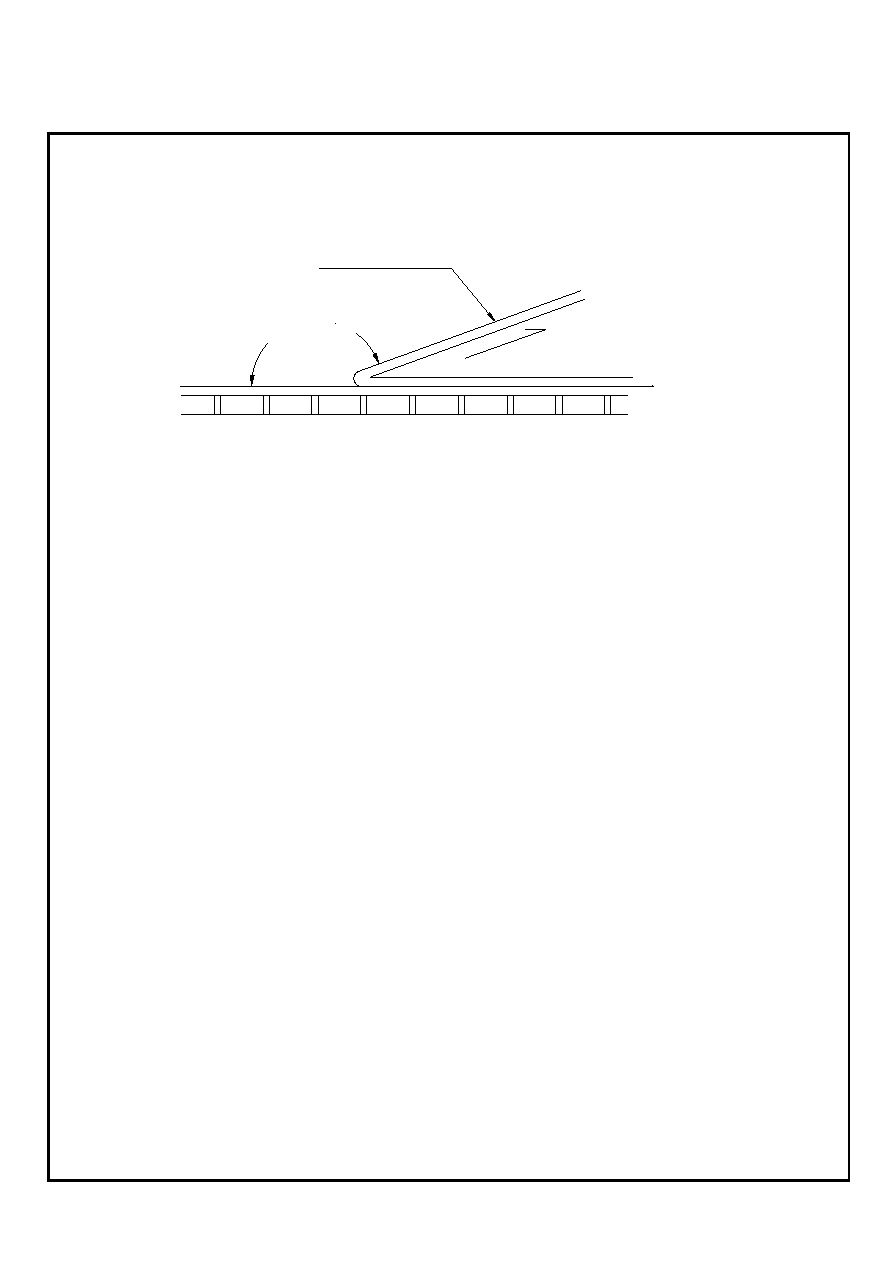
6-2-3 Solderability
A new uniform coating of solder shall cover minimum of 95% of the surface being immersed.
Temperature of solder : 245
± 5
Immersion duration : 2
± 0.5 seconds
Refer to IEC 60115-1 Sub-clause 4.17.
6-2-4 Resistance to Soldering Heat
Resistance Change :
± (0.5%)
Electrical characteristics shall be satisfied.
Without distinct deformation in appearance.
(1) Solder bath method
Pre-heat : 100 to 110 30 seconds
Temperature : 270
± 5 10 ± 1seconds
(2) Reflow Soldering method
Peak temperature : 260
± 5 10 seconds or less
Temperature : 220
± 5 60 seconds max.
The heating apparatus shall be the upper-heated oven and temperature shall be
the board surface temperature.
(3) Soldering iron method
Bit temperature : 350
± 5 3 ± 1/0 seconds
The resistor shall be stored at standard atmospheric conditions for 1 hour, after
which the measurements shall be made.
Refer to IEC 60115-1 Sub-clause 4.18.
R0.5
1/2L
L
Resistor
Pressure rod
Unit : mm

CYNTEC CO., LTD.
DOCUMENT : RLA00000N
REVISION : A2
PAGE : 7 OF 11
6-2-5 Resistance to Solvent
Without mechanical damage and distinct damage in appearance.
Immersion cleaning
At normal temperature 300 seconds in Isopropyl Alcohol.
Refer to IEC 60115-1 Sub-clause 4.29.
6-3 Endurance
6-3-1 Rapid Change of Temperature
Resistance Change :
± (0.5%)
Without distinct damage
Resistance shall be subjected to 5 cycles of the temperature cycle as following :
-55
± 2, 30 minutes room temperature, 2 3 minutes
+125 ± 2, 30 minutes room temperature, 2 3 minutes
Refer to IEC 60115-1 Sub-clause 4.19.
6-3-2 Dump Heat with Load
Resistance Change :
± (1.0%)
Without distinct damage
60
± 2 with relative humidity of 90 to 95%
DC rated voltage for 1.5 hours on 0.5 hour off
1,000 + 48 / - 0 hours
6-3-3 Endurance at 70
Resistance Change :
± (1.0%)
Without distinct damage
70
± 2
DC rated voltage for 1.5 hours on 0.5 hour off
1,000 + 48 / -0 hours
Refer to IEC 60115-1 Sub-clause 4.25.

CYNTEC CO., LTD.
DOCUMENT : RLA00000N
REVISION : A2
PAGE : 8 OF 11
Mounting of the test sample onto the test board shall be either of following methods.
(1) Mounting by solder dipping
Epoxy based glue shall be applied in the middle of two lands of the test board. The
resistor shall be mounted in such a way that the electrodes of resistors will be evenly
placed in the land area and then adhesive resin shall be cured. After applying the Resin
Flux with 25 weight % Methyl Alcohol, the board shall be soldered by dipping into a
molten solder bath with 260
± 5 for 3 to 5 seconds
(2) Mounting by Reflow soldering
Solder paste with approximate 200m thickness shall be applied to the land of test board.
The resistor shall be mounted in such way that the electrodes of resistors will be evenly
placed in the land area and then shall be soldered under the circumstance that the surface
temperature of the board shall be raised 245
± 5(peak) for 5 to 10 seconds in an
upper-heater oven.
Test board A
Material : Glass Fabric Epoxy Resin ( Refer to JIS C 6484 )
Board thickness : 1.6mm
Copper foil thickness : 0.035mm
Solder Resist Coating
40
4.0
100
(3.0)
1.2
1.65
Land
Unit : mm
4.5

CYNTEC CO., LTD.
DOCUMENT : RLA00000N
REVISION : A2
PAGE : 9 OF 11
Test Board B
Material : Glass Fabric Epoxy Resin ( Refer to JIS C 6484 )
Board thickness : 1.6mm
Copper foil thickness : 0.035mm
Solder Resist Coating
2.4
0.4
6.
94
4
27
.0
8.5
18
.5
1
1.32
58.5
(5.08 x 9 = 45.72)
4.46
5.
3
5.08
1.22
Unit : mm

CYNTEC CO., LTD.
DOCUMENT : RLA00000N
REVISION : A2
PAGE : 10 OF 11
7. Packaging
7-1 Dimensions
7-1-1 Tape packaging dimensions
7-1-2 Reel Dimensions
0.75 ± 0.05
0.8 ± 0.1
2.0 ± 0.05
A
B = 2.4 ± 0.2
A = 1.65 ± 0.2
CHIP
1.5
+
0.1
-
0.0
B
4.0 ± 0.1
4.0 ± 0.1
Unit : mm
8.0 ± 0.3
3.5 ± 0.05
1.75 ± 0.1
Pull
Cavity
Label
13 ± 0.2
21 ± 0.8
13 ± 1.4
9 ± 0.3
50
180
+0
-3
R1
2 ± 0.5
105
Unit : mm
60
+1 -0
CYNTEC CO., LTD.
DOCUMENT : RLA00000N
REVISION : A2
PAGE : 11 OF 11
7-2 Peel force of top cover tape
The peel speed shall be about 300 mm/min.
The peel force of top cover tape shall be between 0.1 to 0.7 N.
7-2 Numbers of taping
5,000 pieces/reel
7-3 Label marking
The following items shall be marked on single of the reel.
(1) Type designation .
(2) Quantity
(3) Manufacturing date code
(4) Manufacturer's name
(5) The country of origin
(6) Shipping number
(7) Identification showing lead free products.
7-4 Note
Manufactured by our joint company. ( Susumu Co., Ltd. )
165 ~ 180∞
Top Cover Tape
0.1~0.7 N