 | –≠–ª–µ–∫—Ç—Ä–æ–Ω–Ω—ã–π –∫–æ–º–ø–æ–Ω–µ–Ω—Ç: ADS-231 | –°–∫–∞—á–∞—Ç—å:  PDF PDF  ZIP ZIP |
Æ
Æ
DATEL, Inc., Mansfield, MA 02048 (U.S.A.)
∑
Tel: (508) 339-3000, (800) 233-2765 Fax: (508) 339-6356
∑
Email: sales@datel.com
∑
Internet: www.datel.com
ADS-230/ADS-231
Low-Power, 12-Bit, 1.0/1.5MHz
Sampling A/D Converter
FEATURES
∑
12-bit resolution
∑
1.0 and 1.5MHz throughput rates
∑
Small 44-pin Leaded Chip Carrier
∑
Single +5V supply
∑
Low power, 75 and 200mW maximum
∑
Low power "standby" mode
∑
Outstanding dynamic performance
∑
No missing codes over temperature
∑
Built-in sample-and-hold
∑
Optional two-channel input multiplexer
∑
Ideal for both time and frequency-domain applications
GENERAL DESCRIPTION
The ADS-230 and ADS-231 are 12-bit, high speed CMOS
sampling analog-to-digital converters capable of minimum
sampling rates of 1.0 and 1.5MHz, respectively. Both models
feature excellent dynamic performance including a typical
SNR of 72dB for the ADS-230 and 70dB for the ADS-231.
The ADS-230 and ADS-231 are packaged in a small 44-pin
plastic Leaded Chip Carrier (LCC). Each model contains a
fast-settling sample/hold amplifier, a multipass (three-step
flash) A/D converter, timing and control logic, three-state
outputs, a two-channel multiplexer, and digital error correction
circuitry. Digital input and output levels are TTL.
Requiring only a single +5V supply, the ADS-230 typically
dissipates only 60mW and the ADS-231 only 170mW. Both
models offer a low-power "standby" mode resulting in typical
power dissipations of 100µW and 250µW, respectively. The
units offer a maximum unipolar input range of 0 to +5V. The
exact value of the input range is determined by an externally
applied reference voltage. Both models operate over the
extended ≠40 to +85∞C temperature range.
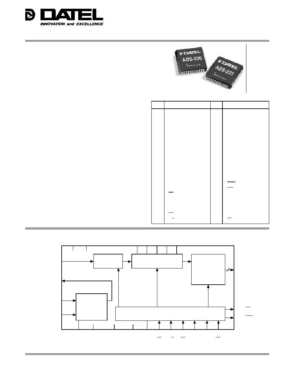
Figure 1. ADS-220/-231 Simplified Block Diagram
1
AGND
44
AV
S
2
V
BS
43
BIT 1 (MSB)
3
V
B
42
BIT 2
4
V
R/16
41
BIT 3
5
V
T
40
BIT 4
6
V
TS
39
BIT 5
7
CH1
IN
38
BIT 6
8
NC
37
BIT 7
9
CH2
IN
36
BIT 8
10
NC
35
BIT 9
11
MUX OUT
34
NC
12
ANALOG INPUT
33
BIT 10
13
AGND
32
BIT 11
14
AV
S
31
BIT 12 (LSB)
15
DGND C
30
EOC
16
SEL
29
INT
17
PD
28
NC
18
DGND C
27
DGND D
19
MD
26
DGND C
20
OE
25
DV
S
21
RD
24
TEST
22
S/H
23
CS
INPUT/OUTPUT CONNECTIONS
PIN
FUNCTION
PIN
FUNCTION
SAMPLE
AND HOLD
12-BIT A/D CONVERTER
OUTPUT LATCH
AND
THREE-STATE
BUFFER
TIMING AND CONTROL CIRCUITRY
MULTIPLEXER
ANALOG INPUT 12
11
7
9
MUX OUT
CH1
IN
CH2
IN
14,44
25
6
5
4
3
2
AV
S
DV
S
V
TS
V
T
V
R/16
V
B
V
BS
16
26,18,15
27
1,13
24
23
22
21
20
19
17
SEL
DGND C
DGND D
AGND
TEST
CS
S/H
RD
OE
MD
PD
EOC
30
INT
29
PIN
43 BIT 1 (MSB)
42 BIT 2
41 BIT 3
40 BIT 4
39 BIT 5
38 BIT 6
37 BIT 7
36 BIT 8
35 BIT 9
33 BIT 10
32 BIT 11
31 BIT 12 (LSB)

ADS-230/ADS-231
2
Æ
Æ
ADS-230
ADS-231
+25∞C
≠40 to +85∞C
+25∞C
≠40 to +85∞C
ANALOG INPUT
TYP.
MIN.
MAX.
TYP.
MIN.
MAX.
UNITS
Input Voltage Range (Pins 7, 9, 12)
--
≠0.05
AV
S
+0.05
--
≠0.05
AV
S
+0.05
V
Input Leakage Current
0.1
--
3
0.1
--
3
µA
Input Capacitance
25
--
--
25
--
--
pF
MUX On/Off-Channel Leakage
0.1
--
3
0.1
--
3
µA
MUX Input Capacitance
7
--
--
7
--
--
pF
MUX Off-Channel Isolation
F
IN
= 100kHz, ≠0dB
92
--
--
92
--
--
dB
REFERENCE INPUT
Reference Input + (Pin 6), V
TS
--
--
AV
S
--
--
AV
S
V
Reference Input ≠ (Pin 2), V
BS
--
0
--
--
0
--
V
Reference Resistance
750
500
1000
750
500
1000
Ohms
DIGITAL INPUT
Logic Levels
Logic "1", V
S
= 5.5V
--
2
--
--
2
--
V
Logic "0", V
S
= 4.5V
--
--
0.8
--
--
0.8
V
Logic Loading "1"
0.1
--
1
0.1
--
1
µA
Logic Loading "0"
0.1
--
1
0.1
--
1
µA
Digital Input Capacitance
4
--
--
4
--
--
pF
S/H Pulse Width , t
S/H
--
5
550
--
5
400
ns
STATIC PERFORMANCE
Resolution
12
12
Bits
Integral Nonlinearity
±0.4
--
±1.5
±0.4
--
±1.5
LSB
Differential Nonlinearity Error
±0.4
--
±0.95
±0.4
--
±0.95
LSB
No Missing Codes
--
12
--
--
12
--
Bits
Offset Error
±0.3
--
±2.0
±0.3
--
±2.0
LSB
Gain Error
±0.2
--
±1.5
±0.3
--
±1.5
LSB
Power Supply Sensitivity, (±10%)
--
--
±1.0
--
--
±0.75
LSB
DYNAMIC PERFORMANCE
Total Harmonic Distortion (≠0dB)
F
IN
= 100kHz
≠82
--
≠70
≠80
--
≠70
dB
Signal-to-Noise Ratio
(wo/distortion, ≠0dB) F
IN
= 100kHz
72
69.5
--
70
67.5
--
dB
Signal-to-Noise Ratio
(& distortion, ≠0dB) F
IN
= 100kHz
71
68
--
70
67
--
dB
Two-Tone Intermodulation Distortion
F
IN
= 102.3, 102.7kHz, (≠0dB)
≠80
--
--
≠80
--
--
dB
Aperature Delay Time, (t
AD
)
20
--
--
20
--
--
ns
A/D Conversion Rate
--
1
--
--
1.5
--
MHz
PARAMETERS
LIMITS
UNITS
Supply Voltages
(V
S
= AV
S
= DV
S
)
≠0.3 to +6
V
Input or Output Voltage, any pin
≠0.3 to V
S
+0.3
V
Input Current, any pin
25
mA
Total Package Input Current,
50
mA
Power Dissipation,
875
mW
ESD Susceptibilty,
2000
V
Soldering, Infrared, 15 seconds
+300
∞C
ABSOLUTE MAXIMUM RATINGS
FUNCTIONAL SPECIFICATIONS
(The following specifications apply for T
A
= T
J
= 25∞C, DV
S
= AV
S
= 5.0V, V
TS
= +4.096V, V
BS
= AGND, R
S
= 25ohms and F
S
= 1.0/1.5MHz for the ADS-230/231 respectively, unless
otherwise specified.)
PHYSICAL/ENVIRONMENTAL
PARAMETERS
MIN.
TYP.
MAX.
UNITS
Operating Temp. Range T
A
= T
J
≠40
--
+85
∞C
Thermal Impedance,
ja
--
55
--
∞C/Watt
Maximum Junction Temp. T
JMAX
--
--
+150
∞C
Storage Temperature Range
≠65
--
+150
∞C
Package Type
44-pin Plastic Leaded Chip Carrier

ADS-230/ADS-231
3
Æ
Æ
ADS-230
ADS-231
+25∞C
≠40 to +85∞C
+25∞C
≠40 to +85∞C
TIMING
TYP.
MIN.
MAX.
TYP.
MIN.
MAX.
UNITS
Conversion Time, t
CONV
740
600
980
580
510
660
ns
Time for Conversion to Start, t
EOC
95
60
125
90
60
125
ns
Access Time, t
ACC
(C
L
= 100pF)
10
--
20
10
--
20
ns
Three-State Control Time, t1H, t0H
R
L
= 1k, C
L
= 10pF
25
--
40
25
--
40
ns
Delay Time, RD Low to INT High
t
INTH
, C
L
= 100pF
35
--
60
35
--
60
ns
Delay Time, EOC High to INT Low
t
INTL
, C
L
= 100pF
25
35
10
25
35
10
ns
EOC High to Data Valid, t
UPDATE
5
--
15
5
--
15
ns
MUX Address Setup Time, t
MS
--
50
--
--
50
--
ns
MUX Address Hold Time, t
MH
--
50
--
--
50
--
ns
CS Setup Time, t
CSS
--
20
--
--
20
--
ns
CS Hold Time, t
CSH
--
20
--
--
20
--
ns
Wake-up Time, t
WU
PD High to First S/H Low
1
--
--
1
--
--
µs
DIGITAL OUTPUT
Logic Levels
Logic "1" (V
S
= 4.5V)
--
2.4
--
--
2.4
--
V
Logic "0", (V
S
= 4.5V)
--
--
0.4
--
--
0.4
V
Logic Loading "1"
--
--
≠360
--
--
≠360
µA
Logic Loading "0"
--
--
1.6
--
--
1.6
mA
Three-State Output Leakage
0.1
--
3
0.1
--
3
µA
Three-State Output Capacitance
5
--
--
5
--
--
pF
Output Coding
Binary
Binary
POWER REQUIREMENTS
Power Supply Range
+5V Supply, V
S
= AV
S
= DV
S
--
4.5
5.5
--
4.75
5.25
V
Power Supply Current
DV
S
Supply Current, DI
S
2
--
3
2
--
3
mA
AV
S
Supply Current, AI
S
10
--
12
32
--
37
mA
Standby Current (AI
S
+DI
S
, PD = 0)
20
--
--
50
--
--
µA
Power Dissipation
--
--
75
--
--
200
mW
Footnotes:
When the input voltage at any pin exceeds the power supply rails (below
GND or Above V
S
) the input current must be limited to ±25mA or less. The
package input current limits to two the number of pins that can meet this
constant.
In most cases, the maximum derated power dissipation will be reached only
during fault conditions.
This is the ESD rating for the human body model, with a 100pF capacitor
discharged through a 1.5 kilohm resistor. The ESD rating for the machine
model is 200V.
For best performance, the rising edge of the S/H pulse must not be near
either the falling or rising edge of EOC. The recommended values of t
S/H
are:
ADS-230: 5ns<t
S/H
<40ns, or 150ns<t
S/H
<550ns
ADS-231: 5ns<t
S/H
<40ns, or 150ns<t
S/H
<400ns
The MUX inputs CH1
IN
and CH2
IN
are not used during dynamic testing of these
models. The internal multiplexer adds harmonic distortion at high input frequencies.
See the Typical Performance Curves for THD with and without the MUX.
The contributions from the first nine harmonics are used in the calculation of THD.
Effective bits is equal to:
(SNR + Distortion ≠ 1.76 + [20 log
Some units may have higher standby currents than the typical indicated. Production
testing of standby current is prohibitive due to the 10 second delay time on DI
S
after
PD is pulled low.
Full Scale Amplitude
Actual Input Amplitude
])
6.02

ADS-230/ADS-231
4
Æ
Æ
PIN DESCRIPTIONS
AV
S
, DV
S
These are the analog and digital power supply input pins. They should all be connected to
the same voltage source. Both AV
S
pins should be bypassed to AGND and the DV
S
pin to
DGNDD. Bypass using a 0.1µF ceramic capacitor in parallel with a 10µF tantalum
capacitor.
AGND, DGNDC, DGNDD
These are the analog and digital ground pins. All of the ground pins should be returned to
the same potential and connected to a stable, noise-free system ground. AGND is the
analog ground. DGNDC is the ground for the digital control lines. DGNDD is the digital
ground for the output data bus.
BIT 1 ≠ BIT 12
These are the three-state data output pins. Output is enabled by RD, CS, and OE.
CH1
IN
, CH2
IN
These are the analog input pins to the internal input multiplexer.
MUX OUT
This is the output of the internal multiplexer,
ANALOG INPUT
This is the direct input to the sampling A to D converter.
SEL
This is the multiplexer channel select pin. The input is selected based on the state of SEL
when EOC transitions low. A low selects channel one and a high selects channel two. See
Table 1.
MD
Connect to DGNDC
TEST
Connect to DV
S
.
CS
This is the Chip Select control input. When low, this pin enables the RD, S/H and OE inputs.
This pin can be tied low.
INT
This is the Interrupt output pin. When using the Interrupt Interface Mode, this output goes
low when a conversion is completed and indicates that the data is available in the output
latches. This output is always high when RD is held low. Refer to the Timing Diagrams.
EOC
This is the End of Conversion output pin. EOC is low during a conversion.
RD
This is the Read control input pin. When RD and CS are low, the INT output is reset and, if
EOC is high, data appears on the data bus. This pin can be tied low.
OE
This is the Output Enable control input pin. The data output pins are in the high impedance
state when OE is low. Data appears when OE is high and CS and RD are both low. This pin
can be tied high.
S/H
This is the Sample and Hold control input pin. When CS is low a new conversion is initiated
by the falling edge of this input.
PD
This is the Power Down control input pin. This pin is held high for normal operation. When
the input is low, the A to D converter goes into power standby mode.
V
R/16
Bypass this pin to AGND using a 0.1µF ceramic capacitor.
VT, VB
These are the positive (top) and negative (bottom) voltage reference force input pins,
respectively.
VTS, VBS
These are the positive (top) and negative (bottom) voltage reference sense pins,
respectively.

ADS-230/ADS-231
5
Æ
Æ
TECHNICAL NOTES
The Analog Input
For maximum performance, the source impedance driving the
input of the ADS-230/-231 should be as low as possible. A
source impedance of less than 100 ohms is recommended.
See the Typical Performance Curves.
If the signal source has high output impedance, the output
should be buffered with an op-amp capable of driving a
switched 25pF/100ohm load. Any ringing or instability of the
op-amp during the sampling period can cause conversion
errors.
Using a high-speed buffer also improves the THD
performance when using the internal MUX. The MUX on-
resistance is non-linear over the range of the input voltage;
this causes the RC time constant of the equivalent circuit
shown in Figure 2 to vary with input voltage. This results in
harmonic distortion with increasing frequency. Inserting a
buffer between the MUX OUT and ANALOG INPUT terminals
will eliminate the loading on R
MUX
and significantly reduce
THD.
The analog input of the ADS-230/-231 can be modeled as
shown in Figure 2. The S/H switch is closed during the sample
period, and open during hold. The hold capacitor (C
H
) has to
be charged to the input voltage by the source within the
sample period. The source impedance (R
S
) will directly effect
the charge time. If R
S
is too large, the voltage across C
H
will
not settle to within Ω LSB's of the source voltage before
conversion begins. This will result in conversion errors.
The combination of R
S
, R
MUX
, R
SW
and C
H
form a low-pass
filter. Therefore, minimizing R
S
will increase the frequency
response of the converter.
The settling time to n bits is:
t
SETTLE
= (R
S
+ R
MUX
+ R
SW
) * C
H
* n * In(2)
The bandwidth of the input circuit is:
F (≠3dB) = 1/[2 * 3.14 * (R
S
+ R
MUX
+ R
SW
) * C
H
]
Internal Multiplexer
Both the ADS-230 and ADS-231 have an internal multiplexer
that is controlled by the logic level on the SEL pin when EOC
goes low. See the timing diagrams. The MUX setup and hold
times can be determined from the following:
t
MS(wrt S/H)
= t
MS
≠t
EOC (min)
t
MS(wrt S/H)
= 50≠60
t
MS(wrt S/H)
= ≠10ns
t
MH(wrt S/H)
= t
MH
+ t
EOC (max)
t
MH(wrt S/H)
= 50 +125
t
MH(wrt S/H)
= 175ns
Note that the ≠10ns indicates that data on SEL must be valid
within 10ns of the S/H pulse going low in order to meet the
setup time requirements. SEL must be valid for the length of
time determined by the following equation:
(t
MS
+ t
EOC(max)
) ≠ (t
MS
≠ t
EOC (min)
) = 185ns
Table 1. Internal Multiplexer Programming
SEL
Channel
0
CH1IN
1
CH2IN
Figure 3. Reference Force Input Only
Figure 2. ADS-230/-231 Input Stage Model
Table 1 shows the coding for MUX channel selection.
The output of the MUX is available at the MUX OUT pin. This
output allows the user to perform additional signal processing,
such as buffering, filtering or gain, before the signal is brought
to the ANALOG INPUT pin. If signal processing is not required
connect the MUX OUT pin directly to the ANALOG INPUT pin.
CH1
IN
TO COMPARATORS
ADS-230/231
R
MUX
CH2
IN
MUX OUT
ANALOG
INPUT
R
S
V
SOURCE
S/H
SWITCH
R
SW
C
H
TYPICAL VALUES
R
MUX
= 100
R
SW
= 100
C
H
= 25pF
4.096V
+5V ±5%
60
V
TS
V
T
10µF
0.1µF
NC
4.093V
V
R/16
0.1µF
REFERENCE
LADDER
ADS-230/231
V
B
V
BS
0.003V
NC