DATEL, Inc., Mansfield, MA 02048 (USA)
∑
Tel: (508)339-3000, (800)233-2765 Fax: (508)339-6356
∑
Email: sales@datel.com
∑
Internet: www.datel.com
Dual Output
BMP Models
High-Efficiency, Smaller-Package
25-40 Watt, DC/DC Converters
Features
DATEL's BMP Models are fully potted, 25-40 Watt, dual-output DC/DC converters
designed to meet UL1950 and EN60950 safety standards. The
combination the BMP's higher efficiencies and thermally conductive potting compound
enables these devices to achieve higher operating temperatures
without derating. The 2" x 3" BMP "footprint" conforms to the standard pinout
and pin geometries of most 3" x 3" devices (a 33% space savings) while
delivering 60% more power (40W vs. 25W).
Applicable to a wide range of telecom, computer and other OEM applications, BMP
Model DC/DC's offer ±5V, ±12V and ±15V outputs. They operate from four different input
voltage ranges with total available output being a function of the selected range. "Q12"
models operate from 10-36V and deliver 25W. "Q48" models operate from 18-75V and
deliver 30W. For "D24" and "D48" models, the input ranges and output powers are 18-
36V at 35W and 36-75V at 40W, respectively.
These devices employ corrosion-resistant metal cases with plastic headers.
Heat-generating transformer cores and power semiconductors are mounted directly to
the cases, which have threaded inserts for optional add-on heat sinks or pcb mounting.
Temperature derating information is provided for operation with and without heat sinks
and forced air flow.
All devices feature input pi filters, input overvoltage shutdown, output overvoltage
protection, output current limiting, and thermal shutdown. UL, CSA, EN and IEC
compliance testing is currently in progress (75V-input devices will be CE marked) as
are full EMI/EMC characterizations. Contact DATEL for the latest available information.
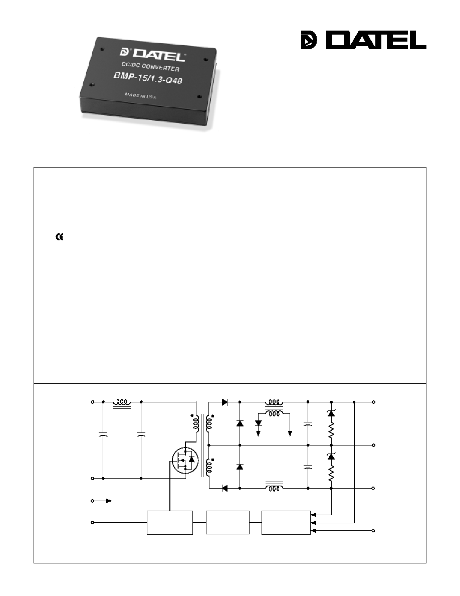
Figure 1. Simplified Schematic
OPTO
ISOLATION
REFERENCE &
ERROR
AMPLIFIER
PWM
CONTROLLER
+V
IN
≠
V
IN
ON/OFF
CONTROL
(SYNC)
TRIM
COMMON
+V
OUT
≠
V
OUT
CASE
≠
V
IN
PWM
INNOVATION and EX C ELL E N C E
Æ
Æ
Higher operating temperatures
Fully potted
Designed to meet UL1950 and
EN60950 (basic insulation)
mark available (75V-input models)
Fully isolated, 1500Vdc guaranteed
25/30/35/40W output power
Standard pinout! Smaller size!
New 2" x 3" package fits 3" x 3" footprint
±5V, ±12V or ±15V outputs
Four input voltage ranges:
10-36V, 18-36V
18-75V, 36-75V
High efficiencies (to 88%)
Fully I/O protected
V
OUT
trim and on/off control
Modifications and customs for OEM's

2 5 - 4 0 W , D U A L O U T P U T D C / D C C O N V E R T E R S
XMP Series
7
6
8
9
4
1
2
3
5
10
METAL
CASE
BOTTOM VIEW
INSULATED
BASE
(4) THREADED INSERTS
#4-40 THD THRU
1.200
(30.48)
2.500
(63.50)
2.04
(51.82)
0.20 MIN
(5.08)
1.600
(40.64)
4 EQ. SP. @
0.400 (10.16)
0.55
(13.97)
0.040 ±0.002 DIA.
(1.016 ±0.051)
2.600
(66.04)
0.22
(5.59)
0.22
(5.59)
0.27
(6.86)
0.42
(10.67)
3.04
(77.22)
DIMENSIONS ARE IN INCHES (MM)
2
As shown below, BMP Model DC/DC Converters are classified by output
power. For dual-output devices, the total output power from the two outputs
can not exceed the rated power. For example, "Q48" models have a
maximum output power of 30W. Therefore, if the +Output is sourcing 20
Watts, the ≠Output is limited to sourcing 10 Watts ensuring the total output
power does not exceed 30 Watts.
Output Configuration:
B = Bipolar
Nominal Output Voltages:
±5, ±12 or ±15 Volts
5
B MP
4
-
/
D48
-
Input Voltage Range:
Q12 = 10-36 Volts (24V nominal)
D24 = 18-36 Volts (24V nominal)
Q48 = 18-75 Volts (48V nominal)
D48 = 36-75 Volts (48V nominal)
Maximum Output Current
in Amps from each output
Fully Potted Metal Package
Typical at T
A
= +25∞C under nominal line voltage and balanced "full-load" conditions unless otherwise noted.
For BMP devices, "full load" is a function of each device's input voltage range. See Output Power Considerations and Technical Notes for more details.
Ripple/Noise (R/N) measured over a 20MHz bandwidth.
Balanced loads, 10% to 100% load.
Nominal line voltage, no-load/full-load conditions.
Performance Specifications and Ordering Guide
R/N (mVp-p)
Load
V
OUT
(Volts)
Package
(Case,
Pinout)
Efficiency
Regulation (Max.)
Line
V
IN
Nom.
(Volts)
Range
(Volts)
Model
I
IN
(mA)
Max.
Typ.
Typ.
Min.
BMP-5/4-Q12
±5
±4
60
120
±0.5%
±1%
24
10-36
15/1225
82%
85%
C11, P15
BMP-5/4-D24
±5
±4
75
125
±0.5%
±1%
24
18-36
15/1696
84%
86%
C11, P15
BMP-5/4-Q48
±5
±4
75
125
±0.5%
±1%
48
18-75
25/735
82%
85%
C11, P15
BMP-5/4-D48
±5
±4
75
125
±0.5%
±1%
48
36-75
20/980
83%
85%
C11, P15
BMP-12/1.65-Q12
±12
±1.65
60
100
±0.5%
±1%
24
10-36
20/1224
83%
85%
C11, P15
BMP-12/1.65-D24
±12
±1.65
60
100
±0.5%
±1%
24
18-36
15/1667
85%
87%
C11, P15
BMP-12/1.65-Q48
±12
±1.65
60
100
±0.5%
±1%
48
18-75
15/727
84%
86%
C11, P15
BMP-12/1.65-D48
±12
±1.65
75
125
±0.5%
±1%
48
36-75
15/948
85%
87%
C11, P15
BMP-15/1.3-Q12
±15
±1.3
60
125
±0.5%
±1%
24
10-36
20/1225
83%
85%
C11, P15
BMP-15/1.3-D24
±15
±1.3
60
125
±0.5%
±1%
24
18-36
15/1648
85%
88%
C11, P15
BMP-15/1.3-Q48
±15
±1.3
60
125
±0.5%
±1%
48
18-75
15/735
83%
85%
C11, P15
BMP-15/1.3-D48
±15
±1.3
60
125
±0.5%
±1%
48
36-75
20/934
84%
87%
C11, P15
I
OUT
(Amps)
P A R T N U M B E R S T R U C T U R E
Model
Maximum Output Power
Q12
25 Watts
Q48
30 Watts
D24
35 Watts
D48
40 Watts
I/O Connections
Function P15
No Pin
≠Input
+Input
Case
On/Off Control*
≠Output
No Pin
Common
+Output
Trim
Pin
1
2
3
4
5
6
7
8
9
10
* See note 4 on next page.
M E C H A N I C A L S P E C I F I C A T I O N S
Case C11
2.600
(66.04)
0.20
(5.08)
2.00
(50.80)
1.200
(30.48)
3.00
(76.20)
0.50
(12.70)
0.40
(10.16)
0.10
(2.54)
0.120 DIA. (3.048)
(4 PLACES)
MATERIAL: BLACK ANODIZED ALUMINUM
4 MOUNTING SCREWS AND 0.009 (0.229) THERMAL PAD INCLUDED
TOP VIEW
Optional Heat Sink (Part Number HS-23)
O U T P U T P O W E R C O N S I D E R A T I O N S
Output
Input

BMP Models
2 5 - 4 0 W , D U A L O U T P U T D C / D C C O N V E R T E R S
3
Floating Outputs
Since these are isolated DC/DC converters, their outputs are "floating." Any
BMP model may be configured to produce an output of 10V, 24V or 30V (for
±
5V,
±
12V or
±
15V models, respectively) by applying the load across the
+Output and ≠Output (pins 9 and 6), with either output grounded. The
Common (pin 8) should be left open. Minimum 20% loading is recom-
mended under these conditions. The total output voltage span may be
externally trimmed as described below.
Performance/Functional Specifications
Typical @ T
A
= +25∞C under nominal line voltage and "full-load" conditions, unless noted.
Input
Input Voltage Range:
Q12 Models
10-36 Volts (24V nominal)
D24 Models
18-36 Volts (24V nominal)
Q48 Models
18-75 Volts (48V nominal)
D48 Models
36-75 Volts (48V nominal)
Input Current
See Ordering Guide
Input Filter Type
Pi
Overvoltage Shutdown:
Q12 and D24 Models
40 Volts
Q48 and D48 Models
80 Volts
Reverse-Polarity Protection
Yes (Instantaneous, 6A maximum)
On/Off Control (Pin 5)
TTL high (or open) = on, low = off
Output
V
OUT
Accuracy (50% load)
±1%, maximum
Temperature Coefficient
±0.02% per ∞C
Ripple/Noise (20MHz BW)
See Ordering Guide
Line/Load Regulation
See Ordering Guide
Efficiency
See Ordering Guide
Isolation Voltage
1500Vdc, minimum
Isolation Capacitance
620pF
Current Limiting
Continuous, auto-recovery
Overvoltage Protection
Zener/transorb clamps, magnetic feedback
Dynamic Characteristics
Transient Response (50% load step)
300µsec max. to ±1.5% of final value
Switching Frequency
125kHz (±10%)
Environmental
Operating Temperature (ambient):
Without Derating
≠40 to +60∞C (Model dependent)
With Derating
to +90∞C (See Derating Curves)
Maximum Case Temperature
+90∞C
Storage Temperature
≠40 to +105∞C
Physical
Dimensions
2.04" x 3.04" x 0.55" (51.8 x 77.2 x 14mm)
Shielding
5-sided
Case Connection
Pin 4
Case Material
Aluminum, black anodized finish
with plastic header
Pin Material
Brass, solder coated
Weight
6 ounces (170 grams)
These converters require a minimum 10% loading on each output to maintain
specified regulation. Operation under no-load conditions will not damage these devices;
however they may not meet all listed specifications.
"Full load" varies by part number and is determined by the input voltage range as indicated by
the part number suffix. See Technical Notes and Output Power Considerations.
Application-specific input/output filtering can be recommended or perhaps added internally
upon request. Contact DATEL Applications Engineering for details.
Applying a voltage to the On/Off Control pin when no input power is applied to the converter
can cause permanent damage to the converter. If desired, the On/Off Control function can be
replaced with a Sync function. See page 6 of this data sheet for more details.
Listed specification is for input-to-output isolation. Input-to-case and output-to-case
isolation is 1000Vdc, minimum.
Filtering and Noise Reduction
All BMP 25-40 Watt DC/DC Converters achieve their rated ripple and noise
specifications without the use of external input/output capacitors. In critical
applications, input/output ripple and noise may be further reduced by
installing electrolytic capacitors across the input terminals and/or low-ESR
tantalum or electrolytic capacitors across the output terminals. Output
capacitors should be connected between their respective output pin (pin 6 or
9) and Common (pin 8). See Figure 7. The caps should be located as close
to the converters as possible. Typical values are listed in the below. In many
applications, using values greater than those listed will yield better results.
To Reduce Input Ripple
"Q12, D24" Models
47µF, 50V
"Q48, D48" Models
10µF, 100V
To Reduce Output Ripple
±5V Outputs
47µF, 10V, Low ESR
±12/15V Outputs
22µF, 20V, Low ESR
In critical, space-sensitive applications, DATEL may be able to tailor the
internal input/output filtering of these devices to meet your specific require-
ments. Contact our Applications Engineering Group for additional details.
Input Voltage:
Q12/D24 Models
44 Volts
Q48/D48 Models
88 Volts
Input Reverse-Polarity Protection
Current must be <6A. Brief
duration only. Fusing recommended.
Output Overvoltage Protection
±5V Outputs
6.8 Volts, limited duration
±12V Outputs
15 Volts, limited duration
±15V Outputs
18 Volts, limited duration
Output Current
Current limited. Max. current and
short-circuit duration are model
dependent.
Storage Temperature
≠40 to +105∞C
Lead Temperature (soldering, 10 sec.)
+300∞C
These are stress ratings. Exposure of devices to any of these conditions may adversely
affect long-term reliability. Proper operation under conditions other than those listed in the
Performance/Functional Specifications Table is not implied.
Absolute Maximum Ratings
T E C H N I C A L N O T E S
V
IN
Range
Q12
D24
Q48
D48
Fuse Value
4A
4A
3A
2A
Input Fusing

2 5 - 4 0 W , D U A L O U T P U T D C / D C C O N V E R T E R S
XMP Series
4
Temperature Derating and Electrical Performance Curves
Q12 Models (25 Watts)
O
u
tp
u
t
P
o
w
e
r (W
a
t
ts
)
Ambient Temperature (∞C)
25
20
15
10
5
0
Natural Convection Cooling
150 Linear Feet Per Minute
300 Linear Feet Per Minute
≠40 0 20 25 30 35
40
45 50 55 60 65 70 75 80 85 90
O
u
tp
u
t
P
o
w
e
r (W
a
t
ts
)
Ambient Temperature (∞C)
25
20
15
10
5
0
Natural Convection Cooling
150 Linear Feet Per Minute
300 Linear Feet Per Minute
≠40 0 20 25 30 35
40
45 50 55 60 65 70 75 80 85 90
Figure 2a. Temperature Derating Without Heat Sink
Figure 2b. Temperature Derating With Heat Sink
O
u
tp
u
t
P
o
w
e
r (W
a
t
ts
)
Ambient Temperature (∞C)
30
25
20
15
10
5
0
Natural Convection Cooling
150 Linear Feet Per Minute
300 Linear Feet Per Minute
≠40 0 20 25 30 35
40
45 50 55 60 65 70 75 80 85 90
O
u
tp
u
t
P
o
w
e
r (W
a
t
ts
)
Ambient Temperature (∞C)
30
25
20
15
10
5
0
Natural Convection Cooling
150 Linear Feet Per Minute
300 Linear Feet Per Minute
≠40 0 20 25 30 35
40
45 50 55 60 65 70 75 80 85 90
Figure 3a. Temperature Derating Without Heat Sink
Figure 3b. Temperature Derating With Heat Sink
Q48 Models (30 Watts)
O
u
tp
u
t
P
o
w
e
r (W
a
t
ts
)
Ambient Temperature (∞C)
35
30
25
20
15
10
5
0
Natural Convection Cooling
150 Linear Feet Per Minute
300 Linear Feet Per Minute
≠40 0 20 25 30 35
40
45 50 55 60 65 70 75 80 85 90
O
u
tp
u
t
P
o
w
e
r (W
a
t
ts
)
Ambient Temperature (∞C)
35
30
25
20
15
10
5
0
Natural Convection Cooling
150 Linear Feet Per Minute
300 Linear Feet Per Minute
≠40 0 20 25 30 35
40
45 50 55 60 65 70 75 80 85 90
Figure 4a. Temperature Derating Without Heat Sink
Figure 4b. Temperature Derating With Heat Sink
D24 Models (35 Watts)

BMP Models
2 5 - 4 0 W , D U A L O U T P U T D C / D C C O N V E R T E R S
5
40
35
30
25
20
15
10
5
0
O
u
tp
u
t
P
o
w
e
r (W
a
t
ts
)
Ambient Temperature (∞C)
≠40 0 20 25 30 35
40
45 50 55 60 65 70 75 80 85 90
Natural Convection Cooling
150 Linear Feet Per Minute
300 Linear Feet Per Minute
Figure 5a. Temperature Derating Without Heat Sink
Figure 5b. Temperature Derating With Heat Sink
D48 Models (40 Watts)
O
u
tp
u
t
P
o
w
e
r (W
a
t
ts
)
Ambient Temperature (∞C)
40
35
30
25
20
15
10
5
0
≠40 0 20 25 30 35
40
45 50 55 60 65 70 75 80 85 90
Natural Convection Cooling
150 Linear Feet Per Minute
300 Linear Feet Per Minute
Temperature Derating and Electrical Performance Curves
Voltage
Output
Model Number
Range
Power
±5V Currents
±12V Currents
±15V Currents
BMP-5/4-Q12
10-36V
25 Watts
±2.5A (25W)
≠
≠
BMP-5/4-Q48
18-75V
30 Watts
±3A (30W)
≠
≠
BMP-5/4-D24
18-36V
35 Watts
±3.5A (35W)
≠
≠
BMP-5/4-D48
36-75V
40 Watts
±4A (40W)
≠
≠
BMP-12/1.65-Q12
10-36V
25 Watts
≠
±1.04A (24.96W)
≠
BMP-12/1.65-Q48
18-75V
30 Watts
≠
±1.25A (30W)
≠
BMP-12/1.65-D24
18-36V
35 Watts
≠
±1.46A (35W)
≠
BMP-12/1.65-D48
36-75V
40 Watts
≠
±1.67A (40.1W)
≠
BMP-15/1.3-Q12
10-36V
25 Watts
≠
≠
±833mA (24.99W)
BMP-15/1.3-Q48
18-75V
30 Watts
≠
≠
±1A (30W)
BMP-15/1.3-D24
18-36V
35 Watts
≠
≠
±1.17A (35.1W)
BMP-15/1.3-D48
36-75V
40 Watts
≠
≠
±1.33A (39.9W)
Definition of "Full Load" for Specification Purposes
Output Power
BMP Model, dual-output DC/DC converters incorporate a design tradeoff
between total available output power and input voltage range. The total
available power is a function of both the nominal input voltage and the
"width" of the input voltage range. For a given nominal input (24V or 48V),
narrower ranges (2:1 vs. 4:1) have more available power. For a given "width"
of input range (2:1 or 4:1), higher nominal inputs (48V vs. 24V) have more
available power. Each device, as indicated by its part-number suffix (Q12, Q48,
D24 or D48) has a total output power limitation of 25, 30, 35 or 40 Watts,
respectively. Observing these power limitations is the user's responsibility.
As indicated by its Part Number Structure, each ±5V, ±12V or ±15V BMP
device is capable of sourcing up to ±4, ±1.65 or ±1.3 Amps, respectively.
Users have the flexibility of loading either output up to these limits; however
you must be extremely careful not to exceed the total output power rating of
any given device. If, for example, a ±5V device with a 30W power rating
(BMP-5/4-Q48) is sourcing 4A from its +5V output (representing 20W of
+Output power), that device can only supply an additional 10W (2 Amps)
from its ≠Output.
As a consequence of this "power-allocation" flexibility, the definition of "full
load," as the condition under which performance specifications are tested and
listed, is ambiguous. The following table lists the positive and negative output
currents that DATEL uses to define each device's "full load."
Table 1. Output Currents Comprising "Full Load"