Dual Output
BMP Models
5V and 3.3V, 2" x 3"
35 Watt, DC/DC Converters
Features
For your moderate-power mixed-logic designs, DATEL's BMP-5/5-3.3/4-D24
(18-36V input) and BMP-5/5-3.3/4-D48 (36-75V input) are fully isolated DC/DC
converters providing both 5V and 3.3V outputs. Housed in DATEL's standard 2" x 3"
x 0.5" metal packages, these BMP duals can simultaneously source up to 4.7 Amps
from their 5V outputs and up to 3.5 Amps from their 3.3V outputs. Both outputs are
fully isolated (1500Vdc) and independently line (±1.0%) and load (±1.0%) regulated.
Both models feature input pi fi lters, input overvoltage shutdown, input reverse-
polarity protection, output overvoltage protection, output current limiting, and thermal
shutdown. Both outputs are controlled via the On/Off Control function (pin 5). The
5 Volt output can be adjusted ±5%.
BMP Model DC/DC's deliver high effi ciency (82%) and are fully specifi ed for
≠40 to +100∞C operation. Their corrosion-resistant metal cases have non-conductive
baseplates and threaded inserts for easy heat-sink attachment and/or pcb mounting.
These devices satisfy IEC950, UL1950 and EN60950 safety requirements for BASIC
insulation. CE marking is available for "D48" models.
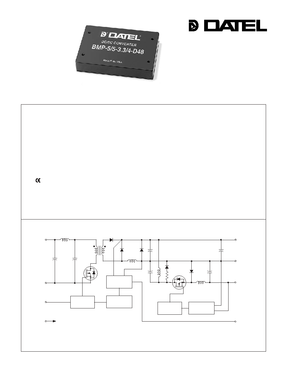
Figure 1. Simplifi ed Schematic
INNOVATION and EX C ELL E N C E
Æ
Æ
Independent 5V @ 4.7A and
3.3V @ 3.5A Outputs
Each output fully regulated
35 Watts total output power
Standard 2" x 3" package
UL1950 and EN60950 safety approvals
(BASIC insulation, -D48 model)
Fully isolated, 1500Vdc guaranteed
18-36V or 36-75V input ranges
mark available (75V-input models)
V
OUT
trim and on/off control
Fully I/O protected
Thermal shutdown
DATEL, Inc., Mansfi eld, MA 02048 (USA) ∑ Tel: (508)339-3000, (800)233-2765 Fax: (508)339-6356 ∑ Email: sales@datel.com ∑ Internet: www.datel.com
PWM
CONTROLLER
+INPUT
≠INPUT
+5V OUTPUT
ON/OFF
CONTROL
(SYNC)
COMMON
+3.3V OUTPUT
CASE
ISOLATION
REFERENCE &
ERROR
AMPLIFIER
TRIM
PWM
CONTROLLER
REFERENCE &
ERROR
AMPLIFIER
3 5 W , D U A L O U T P U T D C / D C C O N V E R T E R S
XMP Series
7
6
8
9
4
1
2
3
5
10
METAL
CASE
BOTTOM VIEW
INSULATED
BASE
(4) THREADED INSERTS
#4-40 THD THRU
1.200
(30.48)
2.500
(63.50)
2.04
(51.82)
0.20 MIN
(5.08)
1.600
(40.64)
4 EQ. SP. @
0.400 (10.16)
0.55
(13.97)
0.040 ±0.002 DIA.
(1.016 ±0.051)
2.600
(66.04)
0.22
(5.59)
0.22
(5.59)
0.27
(6.86)
0.42
(10.67)
3.04
(77.22)
DIMENSIONS ARE IN INCHES (MM)
3.00
(76.20)
2.600
(66.04)
0.20
(5.08)
0.10
(2.54)
0.120 DIA. (3.048)
(4 PLACES)
0.40
(10.16)
0.50
(12.70)
1.200
(30.48)
2.00
(50.80)
TOP VIEW
MATERIAL: BLACK ANODIZED ALUMINUM
4 MOUNTING SCREWS AND 0.009 (0.229) THERMAL PAD INCLUDED
Performance Specifi cations and Ordering Guide
P A R T N U M B E R S T R U C T U R E
V
1
Nominal Output Voltage:
5 Volts
5
BMP
5
-
/
D48
-
Input Voltage Range:
D24 = 18-36 Volts (24V nominal)
D48 = 36-75 Volts (48V nominal)
I
1
Maximum Output Current:
4.7 Amps
Dual Output/
Mixed-Voltage Series
3.3
4
/
-
S
V
2
Nominal Output Voltage:
3.3 Volts
I
2
Maximum Output Current:
3.5 Amps
Add "S" suffi x as desired
Part Number Suffi xes
BMP 35 Watt DC/DC's are designed so an On/Off Control function
with positive polarity (no suffi x) or a Sync function ("S" suffi x) can be
added in the pin 5 position.
No Suffi x On/Off Control function (positive polarity) on pin 5
S Suffi x Sync function on pin 5
BMP-5/5-3.3/4-D24
5 4.7 100 120 ±1% ±1%
24 18-36 35/1870 79% 81% C11, P44
3.3 3.5 100 120 ±1% ±1%
BMP-5/5-3.3/4-D48
5 4.7 100 120 ±1% ±1%
48 36-75 35/923 80% 82% C11, P44
3.3 3.5 100 120 ±1% ±1%
Typical at T
A
= +25∞C under nominal line voltage and "full-load" conditions.
Any combination of 5V/3.3V rated I
OUT
current, not to exceed 35 Watts of output power. (See derating graphs.)
Ripple/Noise (R/N) measured over a 20MHz bandwidth. All models are specifi ed with no output capacitors.
Output
Input
Tested from 10% load to 100% load (other output at fi xed load).
Nominal line voltage, no load/balanced full-power condition.
R/N (mVp-p) Regulation
(Max.)
Effi ciency
Package
V
OUT
I
OUT
V
IN
Nom.
Range
I
IN
(Case,
Model
(Volts) (Amps) Typ. Max. Line Load
(Volts) (Volts) (mA) Min. Typ. Pinout)
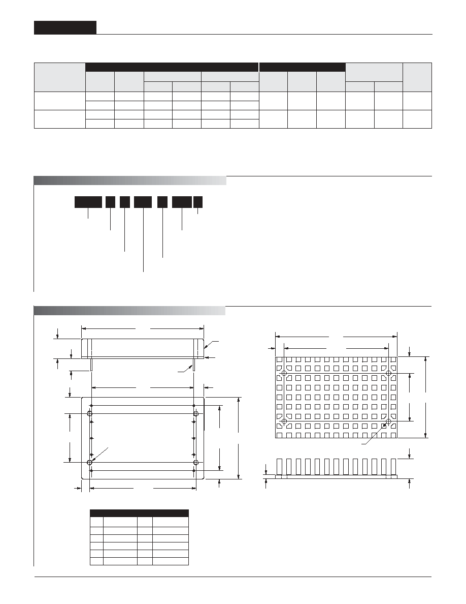
M E C
A N I C A L S P E C I FI C A T I O N S
2
Case C11
I/O
Connections
Pin
Function P44
Pin
Function P44
1
No Pin
6
No Pin
2 ≠Input 7
+3.3V
Output
3
+Input
8 Output
Return
4
Case
9
+5V
Output
5 On/Off
Control 10
Trim
Optional Heat Sink (Part Number HS-23)

BMP Models
3 5 W , D U A L O U T P U T D C / D C C O N V E R T E R S
Performance/Functional Specifi cations
Typical @ T
A
= +25∞C under nominal line voltage, balanced "full-load" conditions, unless noted.
Input
Input Voltage Range:
D24 Models 18-36 Volts (24V nominal)
D48 Models 36-75 Volts (48V nominal)
Overvoltage Shutdown:
D24 Models 36.4-43.6 Volts (40V nominal)
D48 Models 77-85 Volts (83V nominal)
Input Current:
Normal Operating Conditions See Ordering Guide
Standby Mode:
Off, OV, Thermal Shutdown 10mA typical
Input Refl ected Ripple Current:
Source Impedance <0.1
, no external input fi ltering
D24 & D48 Models 100mAp-p (typical)
Internal Input Filter Type Pi (4.5µF - 10µH - 7.5µF)
Reverse-Polarity Protection:
D24 Models 1 minute duration, 3A maximum
D48 Models 1 minute duration, 2A maximum
On/Off Control (Pin 5):
D24 & D48 Models On = open or 2.6V - +V
IN
, I
IN
= 1.5mA max.
Off = 0-1.2V, I
IN
= 1.5mA max.
Output
V
OUT
Accuracy
5V Output ±1% maximum
3.3V Output ±1.5% maximum
Minimum Loading Per Specifi cation 10%
Ripple/Noise (20MHz BW)
See Ordering Guide
Line/Load Regulation See Ordering Guide
Effi ciency See Ordering Guide
Trim Range +5V Output ±5%
Isolation Voltage:
Input-to-Output 1500Vdc minimum
Case-to-Input 1000Vdc minimum
Case-to-Output 1000Vdc mimimum
Isolation Capacitance 470pF
Isolation Resistance 100M
Temperature Coeffi cient ±0.02%/per∞C
Output (continued)
Current Limit Inception:
5V @ 98.5% V
OUT
(3.3V @ 3.5A) 6-8 Amps
3.3V @ 98.5% V
OUT
(5V @ 4.7A) 5-8 Amps
Short Circuit Current:
5V Output 10 Amps average, continuous
3.3V Output 8 Amps average, continuous
Overvoltage Protection: Magnetic feedback/transorb
5V Output 6.8 volts
Dynamic Characteristics
Dynamic Load Response:
5V (50-100% load step to 3% V
OUT
) 300µsec maximum
3.3V (50-100% load step to 3% V
OUT
) 300µsec maximum
Switching Frequency 150kHz (±15kHz)
Environmental
MTBF
Bellcore, ground fi xed, full power, +25∞C
operating ambient temperature
D24 Models TBC million hours
D48 Models TBC million hours
Operating Temperature (Ambient):
No heat sink
Without Derating: ≠40 to +50∞C
With Derating To +100∞C (See Derating Curves)
Case Temperature:
Maximum Operational +100∞C
For Thermal Shutdown +95∞C minimum, +105∞C maximum
Storage Temperature ≠40 to +120∞C
Physical
Dimensions 2.04 x 3.04 x 0.55" (51.8 x 77.2 x 14mm)
Shielding 5-sided
Case Connection Pin 4
Case Material Aluminum, black anodized fi nish
with plastic header
Pin Material Brass, solder coated
Weight: 6 ounces (170 grams)
Primary to Secondary Insulation Level
D24 Models Operational
D48 Models Basic
All models are specifi ed with no external output capacitors.
See Technical Notes/Graphs for details.
Devices may be ordered with On/Off Control function or a Sync function.
See Part Number Suffi xes and Technical Notes for details.
Applying a voltage to On/Off Control (pin 5) when no input power is applied to the
converter may cause permanent damage.
Output noise may be further reduced with the installation of additional external output
capacitors.
On/Off control is designed to be driven with open collector or by appropriate voltage
levels. Voltages must be referenced to the input return pin (≠Input).
Demonstrated MTBF available on request.
3
Absolute Maximum Ratings
Input Voltage:
D24 Models
42 Volts
D48 Models
88 Volts
Input Reverse-Polarity Protection Current must be <3A. Brief duration
only. Fusing recommended.
Output Overvoltage Protection
+5V Outputs
6.8 Volts
Output Current
Current limited. Maximum current and
short-circuit duration are model
dependent.
Storage Temperature
≠40 to +105∞C
Lead Temperature (Soldering, 10 sec.) +300∞C
These are stress ratings. Exposure of devices to any of these conditions may adversely
affect long-term reliability. Proper operation under conditions other than those listed in the
Performance/Functional Specifi cations Table is not implied, nor recommended.

3 5 W , D U A L O U T P U T D C / D C C O N V E R T E R S
XMP Series
4
On/Off Control (Standard)
The On/Off Control pin (pin 5) may be used for remote on/off operation. As
shown in Figure 6, the control pin has an internal 10k
pull-up resistor to
approximately 10V. The converter is designed so that it is enabled when the
control pin is left open (normal mode) and disabled when the control pin is
pulled low (to less than +1.2V relative to ≠Input, pin 2).
Dynamic control of the on/off function is best accomplished with a mechani-
cal relay or an open-collector/open-drain drive circuit (optically isolated if
appropriate). The drive circuit should obviously be able to sink approximately
1.5mA when activated and withstand more than 10 Volts when deactivated.
Applying an external voltage to pin 5 when no input power is applied to the
converter can cause permanent damage to the converter. The on/off control
function, however, is designed such that the converter can be disabled (pin
5 pulled low) while input power is ramping up and then "released" once the
input has stabilized. Under these circumstances, it takes approximately 30ms
for the output of the fully loaded DC/DC to ramp up and settle to within ±1%
of its fi nal value after the converter has been turned on.
Synchronization (Optional)
In critical applications employing multiple switching DC/DC converters, it may
be desirable to intentionally synchronize the switching of selected converters
(so the system noise can be reduced with notch fi ltering) or to purposely
desynchronize the converters (to lessen the current-carrying requirements on
intermediate dc buses). BMP DC/DC Converters have been designed so that
the On/Off Control function on pin 5 can be replaced with a Sync function.
This change has to be implemented by DATEL during the product assembly
process. Contact our Applications Engineering Group for additional details.
To synchronize the switching of multiple BMP converters confi gured with the
Sync function, an external clock can be applied to pin 5 of each converter.
The clock should be a TTL square wave referenced to ≠Input (logic high =
+2 to +5 Volts, 250µA max.; logic low = 0 to +0.8 Volts, 70µA max.) with a
maximum 1µsec "high" duration. The frequency of the synchronizing clock
should be higher than that of any individual converter.
Output Trimming
The total output voltage span of the 5 Volt output, from +5V
Output (pin 9)
to Output Return (pin 8) may be trimmed ±5% via a single trimpot or fi xed
resistor. The trimpot should be connected as shown in Figure 3 with its wiper
connected to pin 10 (Trim). A trimpot can also be used to determine the value
of a single fi xed resistor which can be connected between pin 10 (Trim) and
pin 9 (+5V Output) to trim "down" the output voltages, or between pins 10
(Trim) and 8 (Output Return) to trim "up" the output voltages. Fixed resistors
should have absolute TCR's less than 100ppm/∞C to ensure stability.
Case Connection
Unlike most other DC/DC converters, BMP DC/DC's do not have their metal
case connected to one of their input pins. The "uncommitted" case is con-
nected to pin 4 which, depending on your system confi guration, should be
connected to either +Input (pin 3) or ≠Input (pin 2).
+INPUT
≠INPUT
3
2
+10V
10k
9
5
ON/OFF
CONTROL
20k
5-22
Turns
+INPUT
+5V OUTPUT
+3.3V OUTPUT
TRIM
OUTPUT
RETURN
≠INPUT
3
2
7
9
8
+5V LOAD
+3.3V LOAD
10
+INPUT
+5V OUTPUT
+3.3V OUTPUT
TRIM
OUTPUT
RETURN
≠INPUT
3
2
7
9
8
+5V LOAD
+3.3V LOAD
10
R
TRIM DOWN
+INPUT
+5V OUTPUT
+3.3V OUTPUT
TRIM
OUTPUT
RETURN
≠INPUT
3
2
7
9
8
+5V LOAD
+3.3V LOAD
10
R
TRIM UP
Figure 2. Driving the On/Off Control Pin
Figure 3. +5V
OUT
Trim Connections Using A Trim Pot
Figure 4. +5V
OUT
Trim Down Connections Using A Fixed Resistor
Figure 5. +5V
OUT
Trim Up Connections Using A Fixed Resistor
Note: Resistor values are in k
. Accuracy of adjustment is subject to
tolerances of resistors and factory-adjusted output accuracy.
V
O
= desired output voltage.
DOWN
5 ≠ V
O
R
T
(k
) =
≠16.2
2.49(V
O
≠ 2.53)
UP
V
O
≠ 5
R
T
(k
) =
≠16.2
6.30
BMP Models
3 5 W , D U A L O U T P U T D C / D C C O N V E R T E R S
DATEL makes no representation that the use of its products in the circuits described herein, or the use of other technical information contained herein, will not infringe upon existing or future patent rights. The descriptions contained herein do
not imply the granting of licenses to make, use, or sell equipment constructed in accordance therewith. Specifi cations are subject to change without notice. The DATEL logo is a registered DATEL, Inc. trademark.
DATEL (UK) LTD. Tadley, England Tel: (01256)-880444
DATEL S.A.R.L. Montigny Le Bretonneux, France Tel: 01-34-60-01-01
DATEL GmbH M¸nchen, Germany Tel: 89-544334-0
DATEL KK Tokyo, Japan Tel: 3-3779-1031, Osaka Tel: 6-6354-2025
DATEL, Inc. 11 Cabot Boulevard, Mansfi eld, MA 02048-1151
Tel: (508) 339-3000 (800) 233-2765 Fax: (508) 339-6356
Internet: www.datel.com Email: sales@datel.com
ISO 9001 REGISTERED
INNOVATION and EX C ELL E N C E
Æ
Æ
DS-0494A 4/01
5
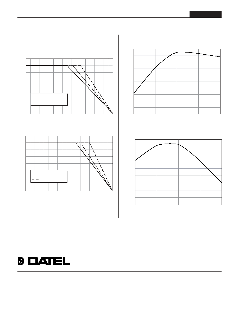
Output P
o
wer (W
atts)
Ambient Temperature (
∞
C)
≠40
0
15
20
25
30
35
40
45
50
55
60
65
70
75 80 85 90 95 100
40
35
30
25
20
15
10
5
0
Natural Convection Cooling
150lfm Air Flow
300lfm Air Flow
Output Power vs. Ambient Temperature
V
IN
= Nominal Without Additional Heat Sink
Output P
o
wer (W
atts)
Ambient Temperature (
∞
C)
≠40
0
15
20
25
30
35
40
45
50
55
60
65
70
75 80 85 90 95 100
40
35
30
25
20
15
10
5
0
Natural Convection Cooling
150lfm Air Flow
300lfm Air Flow
Output Power vs. Ambient Temperature
V
IN
= Nominal With Additional Heat Sink
81.2
81
80.8
80.6
80.4
80.2
80
79.8
79.6
79.4
79.2
BMP-5/5-3.3/4-D24 Efficiency vs. Line Voltage @ Full Load
18
22.5
27
31.5
36
Line Voltage (Volts)
Efficienc
y (
%
)
82.4
82.2
82
81.8
81.6
81.4
81.2
81
80.8
80.6
BMP-5/5-3.3/4-D48 Efficiency vs. Line Voltage @ Full Load
36
45.75
55.5
65.25
75
Line Voltage (Volts)
Efficienc
y (
%
)
Typical Performance Curves
D24 and D48 Models