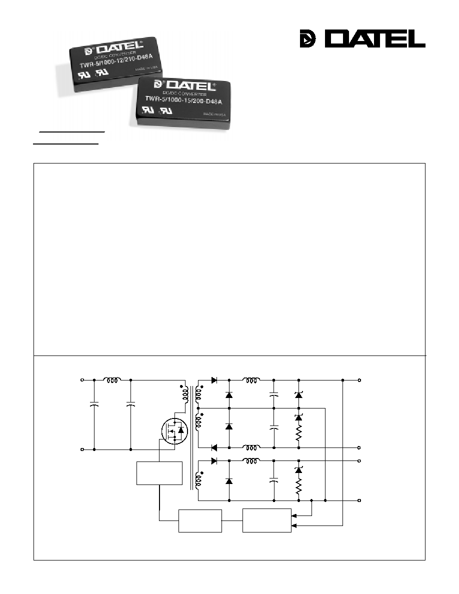
Figure 1. Simplified Schematic
Features
Among the three families of triple-output DC/DC converters in DATEL's new
A-Series, the 8-11W, 2" x 1" devices stand out as the industry's smallest
full-featured triples. Housed in miniature 2" x 1" x 0.375", 5-side shielded, metal
packages with electrically non-conductive coatings, these power converters offer non-
latching output current limiting, input overvoltage shutdown (except D5A models), input
reverse-polarity protection, and output overvoltage clamping to protect both the power
converters and their loads.
As members of DATEL's new A-Series, the 8-11W triples feature both low cost and
outstanding long-term reliability. Their design combines straightforward circuit topolo-
gies, the newest components, proven SMT-on-pcb construction methods, and highly
repeatable automatic-assembly techniques. Their superior durability is substantiated by
a rigorous in-house qualification program that includes HALT (Highly Accelerated Life
Testing).
Each of these fully line and load-regulated switching DC/DC converters has a +5V
primary output (with output current as high as 1A) and either ±12V or ±15V auxiliary
outputs (with currents as high as ±210mA). These devices were designed to power
small analog/digital partitions in equipment employing distributed-power architectures
with bus voltages between 4.7 and 72 Volts. Applications include computer/networking,
telecom/datacom equipment, industrial instrumentation and automatic test equipment.
INNOVATION and EX C ELL E N C E
Æ
Æ
Triple Output
A-Series, TWR Models
High-Reliability, 2" x 1"
8-11 Watt, DC/DC Converters
DATEL, Inc., Mansfield, MA 02048 (USA)
∑
Tel: (508)339-3000, (800)233-2765 Fax: (508)339-6356
∑
Email: sales@datel.com
∑
Internet: www.datel.com
OPTO
ISOLATION
+5V
≠12V (≠15V)
ERROR
AMPLIFIER
PWM
CONTROLLER
+V
IN
≠
V
IN
+12V (+15V)
COMMON
A - S E R I E S
s
s
s
s
s
s
s
s
s
s
s
s
s
s
s
s
s
s
s
s
s
s
s
s
s
s
s
s
s
s
s
s
s
s
s
s
s
s
s
s
s
s
s
s
s
s
s
s
s
s
s
s
s
s
s
s
The smallest, full-featured triples
Low cost! Highly reliable!
Proven SMT-on-pcb construction
Qual tested; HALT tested; EMC tested
Output voltages: +5V/±12V or +5V/±15V
Four input voltage ranges:
4.7-7V, 9-18V, 18-36V or 36-72V
Small packages, 2" x 1" x 0.375"
≠40 to +100∞C operating temperature
Fully isolated, 1500Vdc guaranteed
Guaranteed efficiencies to 82%
Designed to meet UL1950 and EN60950
Modifications and customs for OEM's

8 - 1 1 W , T R I P L E O U T P U T D C / D C C O N V E R T E R S
A Series
A Series
A Series
A Series
A Series
TWR-5/1000-12/125-D5A
TWR-5/1000-12/210-D12A
TWR-5/1000-12/210-D24A
TWR-5/1000-12/210-D48A
TWR-5/800-15/150-D5A
TWR-5/1000-15/200-D12A
TWR-5/1000-15/200-D24A
TWR-5/1000-15/200-D48A
METAL CASE
INSULATED BASE
0.040 ±0.002 DIA.
(1.016 ±0.051)
2.00
(50.80)
0.375
(9.53)
0.20 MIN
(5.08)
0.10
(2.54)
1.800
(45.72)
BOTTOM VIEW
0.200
(5.08)
0.800
(20.32)
0.600
(15.24)
0.300
(7.62)
1.00
(25.40)
1
2
4
5
0.10
(2.54)
6
7
Case C3
2
Function P5
+Input
≠Input
No Pin
+12V/15V Out
≠12V/15V Out
Common
+5V Out
Pin
1
2
3
4
5
6
7
I/O Connections
Output
Configuration:
T = Triple
Nominal Auxiliary Output
Voltages (±12 or ±15 Volts)
Wide Range Input
Maximum Primary Output
Current in mA
Maximum Auxiliary Output
Currents in mA from each output
Input Voltage Range:
D5 = 4.7-7 Volts (5V nominal)
D12 = 9-18 Volts (12V nominal)
D24 =18-36 Volts (24V nominal)
D48 = 36-72 Volts (48V nominal)
Nominal Primary Output
Voltage (+5 Volts)
5
T WR
1000 15 200
-
/
-
/
D12 A
-
A-Series
High Reliability
5
12
24
48
5
12
24
48
+5
±12
+5
±12
+5
±12
+5
±12
+5
±15
+5
±15
+5
±15
+5
±15
Performance Specifications and Ordering Guide
I
OUT
(mA)
R/N (mVp-p)
Load
V
OUT
(Volts)
Output
Package
(Case,
Pinout)
Efficiency
Regulation (Max.)
Line
V
IN
Nom.
(Volts)
Range
(Volts)
Model
Input
I
IN
(mA)
Max.
Typ.
Typ.
Min.
4.7-7
9-18
18-36
36-72
4.7-7
9-18
18-36
36-72
100/2324
50/1087
50/534
50/267
100/2441
50/1187
50/572
50/286
74%
80.5%
82%
82%
74%
79%
82%
82%
C3, P5
C3, P5
C3, P5
C3, P5
C3, P5
C3, P5
C3, P5
C3, P5
1000
±125
1000
±210
1000
±210
1000
±210
800
±150
1000
±200
1000
±200
1000
±200
100
150
100
150
100
150
100
150
100
175
100
175
100
175
100
175
±1.0%
±5.0%
±1.0%
±5.0%
±1.0%
±5.0%
±1.0%
±5.0%
±1.0%
±5.0%
±1.0%
±5.0%
±1.0%
±5.0%
±1.0%
±5.0%
±2.0%
±5.0%
±2.0%
±5.0%
±2.0%
±5.0%
±2.0%
±5.0%
±2.0%
±5.0%
±2.0%
±5.0%
±2.0%
±5.0%
±2.0%
±5.0%
Typical @ T
A
= +25∞C under nominal line voltage and full-load conditions unless otherwise noted.
20MHz bandwidth.
±12/15V outputs are specified with 10µF, 25V output capacitors.
5V output, 10% to 100% load. ±12/15V outputs, balanced loads, 20% to 100% load .
Nominal line voltage, no-load/full-load conditions.
O
u
tp
u
t
P
o
w
e
r (W
a
t
ts
)
Ambient Temperature (∞C)
≠40 0 40 45 50 55 60 65 70 75 80 85 90 95 100
20
19
18
17
16
15
14
13
12
11
10
9
8
7
6
5
4
3
2
1
0
D
B
C
A
TWR-5/1000-12/125-D5A A
TWR-5/1000-12/210-D12A B
TWR-5/1000-12/210-D24A B
TWR-5/1000-12/210-D48A B
TWR-5/800-15/150-D5A C
TWR-5/1000-15/200-D12A
D
TWR-5/1000-15/200-D24A
D
TWR-5/1000-15/200-D48A
D
75
100
75
100
75
100
75
100
75
125
75
125
75
125
75
125
76%
82%
84%
84%
76%
82%
84%
84%
P A R T N U M B E R S T R U C T U R E
M E C H A N I C A L S P E C I F I C A T I O N S
T E M P E R A T U R E D E R A T I N G
Notes:
For "D5A/ D12A/D24A" models,
the case is connected to pin 2 (≠V
IN
).
For "D48A" models, the case
is connected to pin 1 (+V
IN
).

8 - 1 1 W , T R I P L E O U T P U T D C / D C C O N V E R T E R S
TWR Models
3
Filtering and Noise Reduction
All A-Series TWR 8-11 Watt DC/DC Converters achieve their rated ripple and
noise specifications without the use of external input/output capacitors. In
critical applications, input/output ripple and noise may be further reduced by
installing electrolytic capacitors across the input terminals and/or low-ESR
tantalum or electrolytic capacitors across the output terminals. Output
capacitors should be connected between their respective output pin (pin 4, 5 or
7) and Common (pin 6) as shown in Figure 2. The caps should be located as
close to the power converters as possible. Typical values are listed below. In
many applications, using values greater than those listed will yield better
results.
To Reduce Input Ripple
"D5A" Models
47µF, 10V
"D12A" Models
20µF, 25V
"D24A" Models
20µF, 50V
"D48A" Models
10µF, 100V
To Reduce Output Ripple
+5V Output
47µF, 10V, Low ESR
±12/15V Outputs
22µF, 20V, Low ESR
In critical, space-sensitive applications, DATEL may be able to tailor the
internal input/output filtering of these units to meet your specific requirements.
Contact our Applications Engineering Group for additional details.
Performance/Functional Specifications
Typical @ T
A
= +25∞C under nominal line voltage and full-load conditions, unless noted.
These power converters require a minimum 10% loading on their primary output and a
minimum 20% loading on their auxiliary outputs to maintain specified regulation. Operation
under no-load conditions will not damage these devices; however they may not meet all
listed specifications.
Application-specific internal input/output filtering can be recommended or perhaps added
internally upon request. Contact DATEL Applications Engineering for details.
Devices can be screened or modified for higher guaranteed isolation voltages.
Contact DATEL Applications Engineering for details.
On "D48A" models, the case is connected to pin 1 (+V
IN
).
Input
Input Voltage Ranges:
"D5A" Models
4.7-7 Volts (5V nominal)
"D12A" Models
9-18 Volts (12V nominal)
"D24A" Models
18-36 Volts (24V nominal)
"D48A" Models
36-72 Volts (48V nominal)
Input Current
See Ordering Guide
Input Filter Type
Pi
Reverse-Polarity Protection
Yes (Instantaneous, 6A maximum)
Output
V
OUT
Accuracy (50% loads):
+5V Output
±0.5%
±12V or ±15V Outputs
±3%
Temperature Coefficient
±0.02% per ∞C
Ripple/Noise (20MHz BW)
See Ordering Guide
Line/Load Regulation
See Ordering Guide
Efficiency
See Ordering Guide
Isolation Voltage
1500Vdc, minimum
Isolation Capacitance
300pF
Current Limiting
Auto-recovery
Overvoltage Protection
Zener/transorb clamps, magnetic feedback
Dynamic Characteristics
Transient Response (50% load step)
200µsec max. to ±2% of final value
Switching Frequency
175kHz
Environmental
Operating Temperature (Ambient):
Without Derating
≠40 to +60/70∞C (Model dependent)
With Derating
to +100∞C (See Derating Curve)
Storage Temperature
≠40 to +105∞C
Physical
Dimensions
2" x 1" x 0.375" (51 x 25 x 9.5mm)
Shielding
5-sided
Case Connection
Pin 2 (≠V
IN
)
Case Material
Corrosion resistant steel with
non-conductive, epoxy-based, black
enamel finish and plastic baseplate
Pin Material
Brass, solder coated
Weight
1.3 ounces (37 grams)
Input Voltage:
"D5A" Models
10 Volts
"D12A" Models
22 Volts
"D24A" Models
44 Volts
"D48A" Models
80 Volts
Input Reverse-Polarity Protection
Current must be <6A. Brief
duration only. Fusing recommended.
Output Overvoltage Protection
+5V Output
6.8 Volts, limited duration
±12V Outputs
±13 Volts, limited duration
±15V Outputs
±16 Volts, limited duration
Output Current
Current limited.
Max. current and
short-circuit duration model
dependent.
Storage Temperature
≠40 to +105∞C
Lead Temperature (soldering, 10 sec.)
+300∞C
These are stress ratings. Exposure of devices to any of these conditions may adversely
affect long-term reliability. Proper operation under conditions other than those listed in the
Performance/Functional Specifications Table is not implied.
Absolute Maximum Ratings
T E C H N I C A L N O T E S
4
If you're designing with EMC in mind, please note that all of DATEL's TWR
8-11 Watt A-Series DC/DC Converters have been characterized for radiated
and conducted emissions in our new EMI/EMC laboratory. Testing is conducted
in an EMCO 5305 GTEM test cell utilizing EMCO automated EMC test
software. Radiated emissions are tested to the limits of FCC Part 15, Class B
and CISPR 22 (EN 55022), Class B. Correlation to other specifications can be
supplied upon request. Radiated emissions plots to FCC and CISPR 22 for
model TWR-5/1000-12/125-D5A appear below. Published EMC test reports are
available for each model number. Contact DATEL's Applications Engineering
Department for more details.
+INPUT
≠INPUT
+12/15V
1
2
4
6
COMMON
7
C
IN
C
OUT
C
OUT
+
+
+
5
+
C
OUT
+5V
≠12/15V
Figure 2. Using External Capacitors
to Reduce Input/Output Ripple/Noise
Input Fusing
Certain applications and/or safety agencies may require the installation of fuses
at the inputs of power conversion components. For DATEL A-Series TWR 8-11
Watt DC/DC Converters, you should use slow-blow type fuses with values no
greater than 3A.
80
70
60
50
40
30
20
10
0
≠10
≠20
Frequency (MHz)
100
1000
FCC Class B Limit
TWR-5/1000-12/125-D5A Radiated Emissions
FCC Part 15 Class B, 3 Meters
Converter Output = +5Vdc @ 950mA and ±12Vdc @ ±114mA
R
a
d
i
ated
E
m
i
s
si
on
s (dB
µ
V
/
M
)
Radiated Emissions
TWR-5/1000-12/125-D5A Radiated Emissions
EN 55022 Class B, 10 Meters
Converter Output = +5Vdc @ 950mA and ±12Vdc @ ±114mA
80
70
60
50
40
30
20
10
0
≠10
≠20
Frequency (MHz)
100
1000
Radiated Emissions
EN 55022 Class B Limit
R
a
d
i
ated
E
m
i
s
si
on
s (dB
µ
V
/
M
)
DATEL's world-class design, development and manufacturing team stands
ready to work with you to deliver the exact power converter you need for your
demanding, large volume, OEM applications. And ... we'll do it on time and
within budget!
Our experienced applications and design staffs; quick-turn prototype capability;
highly automated, SMT assembly facilities; and in-line SPC quality-control
techniques combine to give us the unique ability to design and deliver any
quantity of power converters to the highest standards of quality and reliability.
We have compiled a large library of DC/DC designs that are currently used in a
variety of telecom, medical, computer, railway, aerospace and industrial
applications. We may already have the converter you need.
Contact us. Our goal is to provide you the highest-quality, most cost-effective
power converters available.
E M I R A D I A T E D E M I S S I O N S
C U S T O M C A P A B I L I T I E S
8 - 1 1 W , T R I P L E O U T P U T D C / D C C O N V E R T E R S
A Series
A Series
A Series
A Series
A Series
5
DATEL makes no representation that the use of its products in the circuits described herein, or the use of other technical information contained herein, will not infringe upon existing or future patent rights. The descriptions contained herein
do not imply the granting of licenses to make, use, or sell equipment constructed in accordance therewith. Specifications are subject to change without notice. The DATEL logo is a registered DATEL, Inc. trademark.
INNOVATION and EX C ELL E N C E
Æ
Æ
DS0324 10/98
DATEL (UK) LTD. Tadley, England Tel: (01256)-880444
DATEL S.A.R.L. Montigny Le Bretonneux, France Tel: 01-34-60-01-01
DATEL GmbH M¸nchen, Germany Tel: 89-544334-0
DATEL KK Tokyo, Japan Tel: 3-3779-1031, Osaka Tel: 6-354-2025
Quality and Reliability
The A-Series are the first DC/DC Converters to emerge from DATEL's new,
company-wide approach to designing and manufacturing the most reliable power
converters available. The five-pronged program draws our Quality Assurance
function into all aspects of new-product design, development, characterization,
qualification and manufacturing.
Design for Reliability
Design for Reliability is woven throughout our multi-phased, new-product-
development process. Design-for-reliability practices are fully documented and
begin early in the new-product development cycle with the following goals:
1. To work from an approved components/vendors list ensuring the use of
reliable components and the rigorous qualification of new components.
2. To design with safety margins by adhering to a strict set of derating
guidelines and performing theoretical worst-case analyses.
3. To locate potential design weaknesses early in the product-development
cycle by using extensive HALT (Highly Accelerated Life Testing).
4. To prove that early design improvements are effective by employing a
thorough FRACA (Failure Reporting Analysis and Corrective Action) system.
HALT Testing
The goal of the accelerated-stress techniques used by DATEL is to force device
maturity, in a short period of time, by exposing devices to excessive levels of
"every stimulus of potential value." We use HALT (Highly Accelerated Life
Testing) repeatedly during the design and early manufacturing phases to detect
potential electrical and mechanical design weaknesses
that could result in possible future field failures.
During HALT, prototype and pre-production DC/DC converters are subjected to
progressively higher stress levels induced by thermal cycling, rate of tempera-
ture change, vibration, power cycling, product-specific stresses (such as dc
voltage variation) and combined environments. The stresses are not meant to
simulate field environments but to expose any weaknesses in a product's
electro/mechanical design and/or assembly processes. The goal of HALT is to
make products fail so that device weaknesses can be analyzed and strength-
ened as appropriate. Applied stresses are continually stepped up until products
eventually fail. After corrective actions and/or design changes, stresses are
stepped up again and the cycle is repeated until the "fundamental limit of the
technology" is determined.
DATEL has invested in a Qualmark OVS-1 HALT tester capable of applying
voltage and temperature extremes as well as 6-axis, linear and rotational,
random vibration. A typical HALT profile (shown above) consists of thermal
cycling (≠55 to +125∞C, 30∞C/minute) and simultaneous, gradually increasing,
random longitudinal and rotational vibration up to 20G's with load cycling and
applied-voltage extremes added as desired. Many devices in DATEL's new A-
Series could not be made to fail prior to reaching either the limits of the HALT
chamber or some previously known physical limit of the device. We also use
the HALT chamber and its ability to rapidly cool devices to verify their "cold-
start" capabilities.
Qualification
For each new product, electrical performance is verified via a comprehensive
characterization process and long-term reliability is confirmed via a rigorous
qualification procedure. The qual procedure includes such strenuous tests as
thermal shock and 500 hour life. Qual testing is summarized below.
In-Line Process Controls and Screening
A combination of statistical sampling and 100% inspection techniques keeps
our assembly line under constant control. Parameters such as solder-paste
thickness, component placement, cleanliness, etc. are statistically sampled,
charted and fine tuned as necessary. Visual inspections are performed by
trained operators after pick-and-place, soldering and cleaning operations. Units
are 100% electrically tested prior to potting. All devices are temperature cycled,
burned-in, hi-pot tested and final-electrical tested prior to external visual
examination, packing and shipping.
Rapid Response to Problems
DATEL employs an outstanding corrective-action system to immediately
address any detected shortcomings in either products or processes. Whenever
our assembly, quality or engineering personnel spot a product/process problem,
or if a product is returned with a potential defect, we immediately perform a
detailed failure analysis and, if necessary, undertake corrective actions. Over
time, this system has helped refine our assembly operation to yield one of the
lowest product defect rates in the industry.
Typical HALT Profile
Qualification Test
Method/Comments
HALT
DATEL in-house procedure
High Temperature Storage
Max. rated temp., 1,000 hours
Thermal Shock
10 cycles, ≠55 to +125∞C
Temperature/Humidity
+85∞C, 85% humidity, 48 hours
Lead Integrity
DATEL in-house procedure
Life Test
+70∞C, 500 hours*
Marking Permanency
DATEL in-house procedure
End Point Electrical Tests
Per product specification
Qualification Testing
* Interim electrical test at 200 hours.
10 20 30 40 50 60 70 80 90
40
20
0
Random
Vi
br
at
i
o
n (
G
'
s
)
Tem
p
er
at
ure (
∞
C
)
Test Time (minutes)
100
80
60
40
20
0
≠20
≠40
DATEL, Inc. 11 Cabot Boulevard, Mansfield, MA 02048-1151
Tel: (508) 339-3000 (800) 233-2765 Fax: (508) 339-6356
Internet: www.datel.com Email: sales@datel.com
Data Sheet Fax Back: (508) 261-2857
ISO 9001
ISO 9001
R E G I S T E R E D
8 - 1 1 W , T R I P L E O U T P U T D C / D C C O N V E R T E R S
TWR Models