FEATURES
optimize board
Low profile package
Built-in strain relief
Glass passivated junction
Low inductance
Excellent clamping capability
Repetition Rate(duty cycle):0.05%
Volts to BV min.
Typical IR less than 1mA above 10V
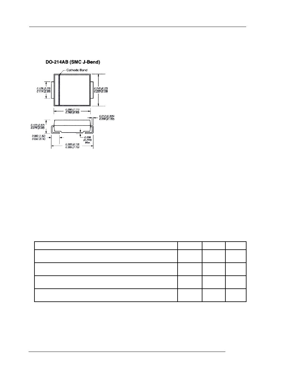
Dimensions in inches and (millimeters)
MECHANICAL DATA
Standard Packaging: 16mm tape(EIA STD RS-481)
Weight: 0.007ounce, 0.21gram
SYMBOL VALUE
UNITS
P
PPM
Minimum
1500
Watts
I
PPM
SEE
TABLE 1
Amps
T
J
, T
STG
-55 to +
150
Notes :
1.Non-repetitive current pulse , per Fig. 3 and derated above T
A
= 25
per Fig. 2 .
2.Mounted on 8.0mm
2
Copper Pads to each terminal
3.8.3ms single half sine-wave , or equivalent square wave, Duty cycle = 4 pulses per minutes maximum.
1.5SMC SERIES
SURFACE MOUNT TRANSIENT VOLTAGE SUPPRESSOR
VOLTAGE-6.8 TO 91 Volts
1500 Watt Peak Pulse Power
Peak Pulse Power Dissipation on 10/1000
s waveform (Note 1,FIG.1)
For surface mounted applications in order to
Fast response time: typically less than 1.0ps from 0
Case: JEDEC DO214AB. Molded plastic over glass passivated junction
Terminal: Solder plated, solderable per MIL-STD-750, Method 2026
High temperature soldering: 250°C/10 seconds at terminals
Polarity: Color band denotes positive end (cathode) except Bidirectional
DEVICES FOR BIPOLAR APPLICATION
For Bidirectional use Suffix CA for types 1.5SMC6.8CA thru types 1.5SMC91CA
Electrical characteristics apply in both directions
Operating junction and Storage Temperature Range
MAXIMUM RATINGS AND CHARACTERISTICS
Ratings at 25
ambient temperature unless otherwise specified.
I
FSM
200
Amps
RATING
Peak Pulse Current of on 10/1000
s waveform (Note 1,FIG.3)
Peak Forward Surge Current,8.3ms Single Half Sine-Wave
Superimposed on Rated Load,(JEDEC Method) (Note 3)
DB LECTRO Inc.
DB LECTRO Inc. 3600 boul. Matte suite i Brossard Qc J4Y-2Z2 tel:(450)-444-1424 fax:(450)-444-4714
Ratings and
Characteristic Curves
(T
A
=25
unless otherwise noted)
1.5SMC SERIES
RATINGS AND CHARACTERISTIC CURVES
10
100
1000
1
10
100
Peak Forward Surge Current,Amperes
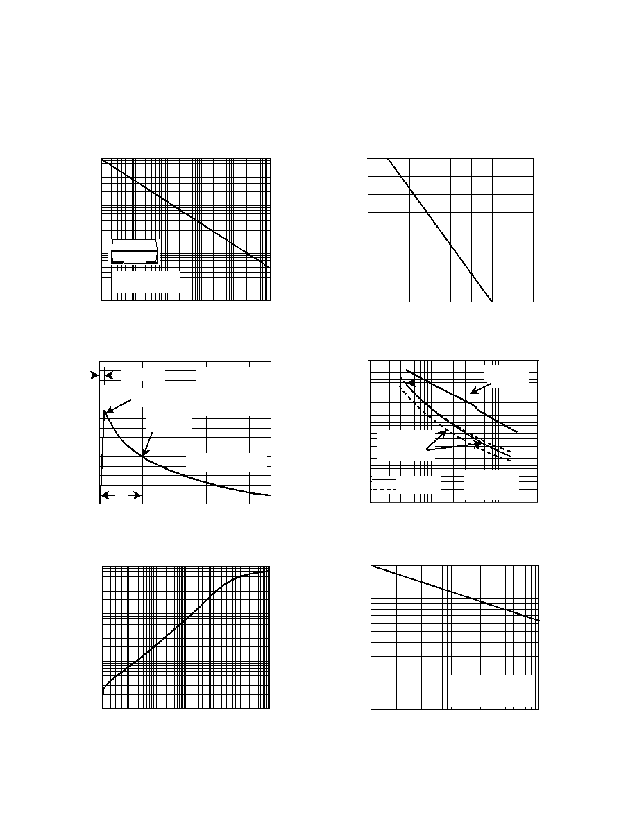
Fig.6 - Maximum Non-Repetitive Forward
Surge Current Uni-Directional Use Only
200
8.3ms Single Half Sine-Wave
(JEDEC Method)
TJ = TJ max,
Number of Cycles at 60 Hz
t - Time(ms)
3.0
4.0
150
0
1.0
2.0
t
r
= 10µsec.
Peak Value
I
PPM
T
J
= 25°C
Pulse Width(td)is defined
as the point where the
peak current decays to
50% of I
PPM
10/1000µsec.Waveform
as defined by R.E.A.
t
d
Fig.3 - Pulse Waveform
4.0
50
Half Value- I
PPM
2
100
I
PPM
- Peak Pulse Current,% I
RSM
3.0
0
0.1
1
10
100
0.001
0.01
0.1
1
10
100
1000
Transient Thermal Impedance
(
/W)
Fig. 5 - Typ.Transient Thermal Impedance
t
p
-Pulse Duration (sec)
1.0
0.1
1
10
100
10ms
0.1µs
1.0µs
10µs
100µs
1.0ms
t
d
- Pulse Width (sec.)
Fig. 1 - Peak Pulse Power Rating
Ppp
M
-Peak Pulse Power (kW)
0.31x0.31"(8.0x8.0mm)
Copper Pad Areas
10
100
1000
10000
100000
0
12.5
25
37.5
50
62.5
75
87.5
100
0
25
50
75
100
125
150
175
200
Fig.2 - Pulse Derating Curve
Peak Pulse Power (P
PP
) or Current (I
PP
)
Derating in Percentage,%
T
A
- Ambient Temperature (°C)
V
WM
- Reverse Stand-Off Voltage (V)
400
C
J
- Junction Capacitance(pF)
1.0
100
10
400
20000
Fig.4 - Typical Junction Capacitance
Uni-Directional
Measured at
Zero Bias
T
J
= 25°C
f = 1.0MH
Z
Vsig = 50mVp-p
V
R
,Measured at
Stand-Off
Voltage, V
WM
Uni-Directional
Bi-Directional
DB LECTRO Inc.
DB LECTRO Inc. 3600 boul. Matte suite i Brossard Qc J4Y-2Z2 tel:(450)-444-1424 fax:(450)-444-4714