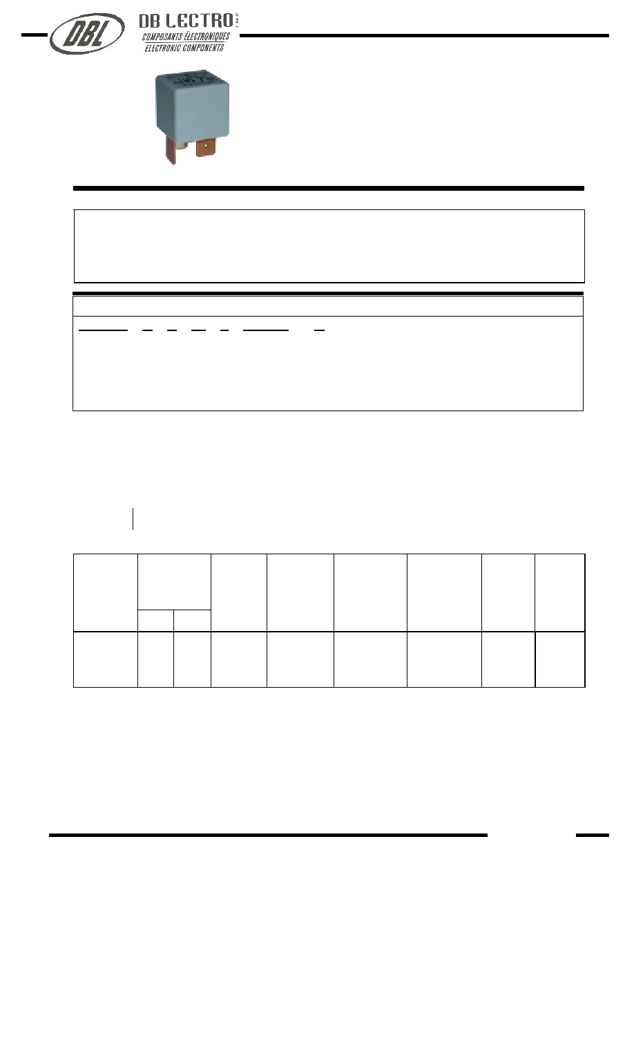
Features
Miniature.
Contact load capacity up to 30A.
Suitable for automobile.
Terminal types as inserting.
Ordering Information
NVF4-5 C Z 30 b DC12V
R
1 2 3 4 5 6 7
1 Part number
NVF4-5
2 Contact arrangement A:1A
3 Enclosure
S: Sealed type
Z: Dust cover
4 Contact Current
30:30A
5 Terminals b: PCB type
a: plug in type
6 Coil rated Voltage(V)
DC:12
7 Coil transient suppression: R: with resistance
NIL: standard
Contact Data
Contact Arrangement
1A SPSTNO
Contact Material
Ag SnO
2
, AgNi
Contact Rating (resistive)
30A/14VDC
Max. Switching Power
420W
Max. Switching Voltage
75VDC Max. Switching Current:30A
Contact Resistance or Voltage drop
100mV (at 30A) Item 3.12 of IEC255-7
Electrical
10
5
Item 3.30 of IEC255-7
Operation
life
Mechanical
10
7
Item 3.31 of IEC255-7
Coil Parameter
Coil voltage
VDC
Dash
number
Rate
d
Max.
Coil
resistance
±
10%
Pickup
voltage
VDC(max)
(67%of rated
voltage )
release
voltage
VDC(min)
(12.5% of
rated voltage)
Coil power
consumption
W
Operate
Time
ms
Release
Time
ms
012-2200
12
15.6
67
8
1.5
2.2
7
5
CAUTION
: 1.The use of any coil voltage less than the rated coil voltage will compromise the operation of the relay.
2.Pickup and release voltage are for test purposes only and are not to be used as design criteria.
137
N V F 4 - 5
26.5
◊
26.5
◊
25
www.dblectro.com

Operation condition
Insulation Resistance
1)
100M min (at 500VDC)
Item 7 of IEC255-5
Dielectric Strength
1)
Between contacts
Between contact and coil
50Hz 500V
50Hz 500V
Item 6 of IEC255-5
Item 6 of IEC255-5
Shock resistance
147m/s
2
11ms
IEC68-2-27 Test Ea
Vibration resistance
10~40Hz double amplitude 1.5mm
IEC68-2-6 Test Fc
Terminals strength
8N
IEC68-2-21 Test Ua2
Solderability
235
x
2
3
x
0.5s
IEC68-2-20 Test Ta method 1
Ambient Temperature
-40~85
Relative Humidity
85% (at 40
)
IEC68-2-3 Test Ca
Mass
30g
Note: 1). When testing, coil terminals shall be connect ,If coil transient suppression is installed in relay .
Qualification inspection:
Perform the qualification test as specified in the table
of IEC255-19-1 and minimum sample size 24.
Dimensions (Unit: mm)
NOTES
1).Dimensions are in millimeter.
2).Inch equivalents are given for general information only.
NVF4-5
Mounting (Bottom views)
Wiring diagram (Bottom views)
Dimensions
mm
>ýÁ«·
0.8
0.031
1.2
0.047
2
0.079
2.8
0.110
4.8
0.189
6.3
0.248
7.5
0.295
8.4
0.331
8.5
0.335
9.5
0.374
10.5
0.413
11
0.433
12
0.472
15
0.591
16
0.669
17.9
0.705
25
0.984
26.5
1.043
◊1.2
◊0.8
◊0.8
www.dblectro.com