TECHNICAL SPECIFICATIONS OF SINGLE-PHASE SILICON BRIDGE RECTIFIER
VOLTAGE RANGE - 50 to 1000 Volts CURRENT - 15 Amperes
MAXIMUM RATINGS AND ELECTRICAL CHARACTERISTICS
Ratings at 25
o
C ambient temperature unless otherwise specified.
Single phase, half wave, 60 Hz, resistive or inductive load.
For capacitive load, derate current by 20%.
BR1505W
THRU
BR1510W
BR-25W
RECTIFIER SPECIALISTS
R
DC COMPONENTS CO., LTD.
Maximum Recurrent Peak Reverse Voltage
Maximum RMS Bridge Input Voltage
Maximum DC Blocking Voltage
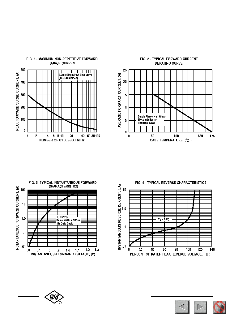
Peak Forward Surge Current 8.3 ms single half sine-wave
superimposed on rated load (JEDEC Method)
SYMBOL
V
RRM
V
DC
I
O
I
FSM
V
RMS
Volts
Volts
Amps
15
300
UNITS
Maximum Average Forward Rectified Output Current at Tc = 55
o
C
50
200
400
100
600
800
1000
35
140
280
70
420
560
700
50
200
400
100
600
800
1000
Volts
Amps
DC Blocking Voltage per element
V
F
I
R
1.1
500
uAmps
Maximum DC Reverse Current at Rated
Maximum Forward Voltage Drop per element at 7.5A DC
Volts
10
Operating and Storage Temperature Range
T
J,
T
STG
-55 to + 150
0
C
NOTES : 1.Measured at 1 MH
Z
and applied reverse voltage of 4.0 volts
2. Thermal Resistance from Junction to Case per leg.
I
2
t Rating for Fusing (t<8.3ms) I
2
t 374 A
2
Sec
Typical Junction Capacitance ( Note1)
C
J
300
pF
Typical Thermal Resistance (Note 2) R
J C 2.5
0
C/W
BR1505W BR151W BR152W BR154W BR156W BR158W BR1510W
@T
A
= 25
o
C
@T
A
= 100
o
C
TYP
METAL HEAT SINK
Dimensions in inches and (millimeters)
FEATURES
* Surge overload ratings-300 Amperes
* Case: Molded plastic with heatsink
MECHANICAL DATA
* Epoxy: UL 94V-0 rate flame retardant
* Lead: MIL-STD-202E, Method 208 guaranteed
* Polarity: As marked
* Mounting position: Any
* Weight: 30 grams
* Plastic case with heatsink for Maximum Heat
* Low forward voltage drop
246
NEXT
BACK
EXIT
NEXT
BACK
EXIT
NEXT
BACK
EXIT