DS30245 Rev 2 - 2
1 of 3
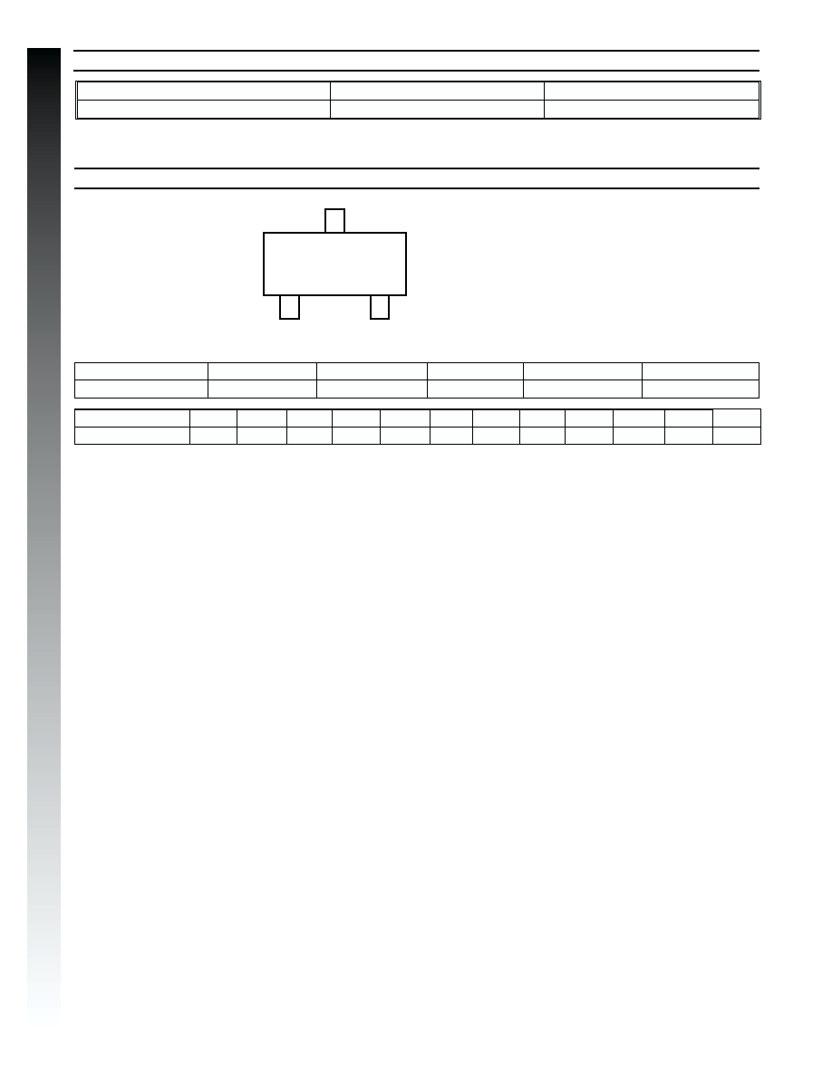
BAT1000
BAT1000
1A SURFACE MOUNT SCHOTTKY BARRIER RECTIFIER
Features
∑
Case: SOT-23, Molded Plastic
∑
Case material - UL Flammability Rating
Classification 94V-0
∑
Moisture sensitivity: Level 1 perJ-STD-020A
∑
Terminals: Solderable per MIL-STD-202,
Method 208
∑
Polarity: See Diagram
∑
Weight: 0.008 grams (approx.)
∑
Marking: K79 and Date Code, See Page 3
∑
Ordering Information: See Page 3
Mechanical Data
Maximum Ratings
@ T
A
= 25∞C unless otherwise specified
∑
Very Low Forward Voltage Drop
∑
High Conductance
∑
For Use in DC-DC Converter, PCMCIA,
and Mobile Telecommunications Applications
Characteristic
Symbol
Value
Unit
Peak Repetitive Reverse Voltage
Working Peak Reverse Voltage
DC Blocking Voltage
V
RRM
V
RWM
V
R
40
V
RMS Reverse Voltage
V
R(RMS)
28
V
Average Rectified Current (Note 1)
I
O
1.0
A
Non-Repetitive Peak Forward Surge Current
8.3ms Single half sine-wave superimposed on rated load
(JEDEC Method)
I
FSM
5.5
A
Power Dissipation (Note 1)
P
d
500
mW
Typical Thermal Resistance, Junction to Ambient Air
(Note 1)
R
qJA
200
∞C/W
Operating Temperature Range
T
j
-40 to +125
∞C
Storage Temperature Range
T
STG
-40 to +150
∞C
Notes:
1. Part mounted on FR-4 board with recommended pad layout, which can be found on ourwebsite
at http://www.diodes.com/datasheets/ap02001.pdf.
2. Short duration pulse test used to minimize self-heating effect.
A
E
J
L
TOP VIEW
M
B C
H
G
D
K
Characteristic
Symbol
Min
Typ
MaxUnit
Test Condition
Reverse Breakdown Voltage (Note 2)
V
(BR)R
40
æ
æ
V
I
R
= 300uA
Forward Voltage (Note 2)
V
F
æ
225
235
290
340
390
420
475
270
290
340
400
450
500
600
mV
I
F
= 50mA
I
F
= 100mA
I
F
= 250mA
I
F
= 500mA
I
F
= 750mA
I
F
= 1000mA
I
F
= 1500mA
Reverse Current (Note 2)
I
R
æ
æ
100
mA
V
R
= 30V
Total Capacitance
C
T
æ
æ
175
25
æ
æ
pF
pF
V
R
= 0V, f = 1.0MHz
V
R
= 25V, f = 1.0MHz
Electrical Characteristics
@ T
A
= 25∞C unless otherwise specified
NEW
P
RODUCT
SOT-23
Dim
Min
Max
A
0.37
0.51
B
1.20
1.40
C
2.30
2.50
D
0.89
1.03
E
0.45
0.60
G
1.78
2.05
H
2.80
3.00
J
0.013
0.10
K
0.903
1.10
L
0.45
0.61
M
0.85
0.80
a
0∞
8∞
All Dimensions in mm

DS30245 Rev 2 - 2
2 of 3
BAT1000
0
0.25
0.50
0
50
100
150
I
,
A
VERA
G
ER
E
C
TIFIED
C
URRENT
(
A
)
O
T , TERMINAL TEMPERATURE ( C)
Fig. 1 Forward Current Derating Curve
T
∞
0.75
1.0
25
75
125
0.01
0.1
1.0
10
0.2
0
0.4
0.6
0.8
1.0
I
,
INST
ANT
ANEOUS
FWD
CURRENT
(A)
F
V , INSTANTANEOUS FORWARD VOLTAGE (V)
Fig. 2 Typical Forward Characteristics
F
T = 25 C
Pulse width = 300 s
2% duty cycle
j
∞
m
C
,
T
O
T
A
L
CAP
ACIT
ANCE
(pF)
T
V , REVERSE VOLTAGE (V)
R
Fig. 3 Typ. Total Capacitance vs Reverse Voltage
1000
1.0
10
100
0
5
10
15
20
25
NEW
P
RODUCT
25
50
75
100
125
150
1
10
20
50
40
30
T
,
AMBIENT
TEMPERA
TURE
(
)
A
∫C
V , REVERSE VOLTAGE (V)
Fig. 4 Typical Safe Operating Area
R
R
= 300 C/W
Note 1
( JA
q
∞
Note: 1. Assumed application thermal conditions.
R
qJA
varies depending on application.